Welcome to part two of my 486 restoration project! In my last post, I took a look at some of the rescued parts from a badly neglected tower. Today, I’ll be going through my adventures of getting a functional CMOS battery working on this system.
As mentioned briefly in part one, most 386 and early 486 systems included what are referred to as ‘barrel batteries’. These are rechargeable nickel cadmium (NiCAD) batteries and are usually rated at 3.6V fully charged. Unlike the coin cell batteries in newer systems, the battery charges whenever the system is powered on. In theory, this was great because the CMOS battery could last a long time in the system. Using a multi-cell rechargeable battery increases the cost of the board, so the CR2032 coin cell solutions were most likely used for cost savings first and foremost in the years following. This is all well and good, but nobody really envisioned these systems to be in use 25 years later as is the case with this system here.
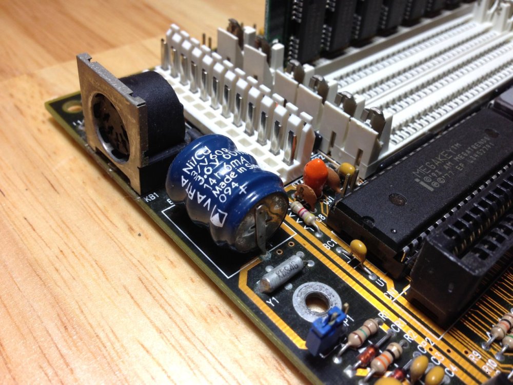
A quick google search on these barrel batteries, and you’ll see just how problematic these can be when they age. Not only can they leak and cease to function, but when they do they are very corrosive to copper traces and other types of metal on the board. If caught early enough, the board can be cleaned and may still be functional. Unfortunately, the damage can sometimes be permanent.
In my search for solutions, I had considered several options, but ultimately I knew this barrel battery had to go.
Probably the best online resource I found on potential options is an article on old CMOS batteries at pc-restorer.com. The article covers options for barrel battery replacement as well as other old types of batteries, like RTC modules. I’d recommend taking a look if you are looking to do something similar.
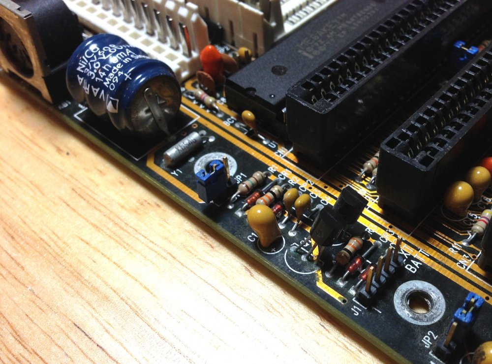
I was very fortunate to find an external battery pack header on the Pine PT429 motherboard. A simple jumper (JP1) is used to disconnect the positive terminal of the battery so that an external battery can be used. This makes the replacement that much easier. I can simply remove the battery from the board, and rig up a 4-pin battery lead instead. Because the external header will not have voltage applied when the system is on – unlike the terminals for the barrel battery – I can use a cheaper, non-rechargable battery here.
The Test
Before deciding on a type of external battery pack to construct, I had to pick a type of battery and target voltage. The Varta barrel battery when fully charged should output about 3.6V. That’s more than the usual 3V coin-cell battery, and quite a bit less than many of the 3xAAA holders rated for 4.5V. I suspect that 4.5V would probably be fine, because while the machine is powered on, the positive battery terminal reads a little under 5V. This higher than rated voltage is for charging purposes, so the circuitry should be able to handle it.
To make things more confusing, I found the PT-429 manual online and discovered that the external battery header is labeled for +6V DC. This is quite a step up from 4.5V, let alone 3.6V.
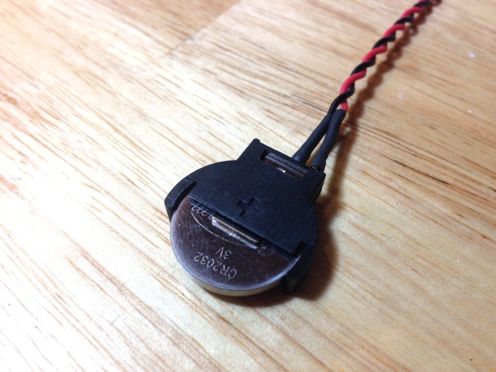
Rather than creating a dual CR2032 or 4xAAA contraption, I decided err on the side of caution. My concern is that many of the CR2032s and AAA batteries measure above their rated voltage when new. Many CR2032s I’ve checked are closer to 3.2V and some AAAs are 1.65V. That would give me a lot closer to 6.5V and I really didn’t want to push it. I decided to try things out with a single CR2032 coin cell battery rated at 3V instead. If it worked reliably, I’d construct something a bit sturdier. 3.6V from the Varta battery is clearly enough to keep things working, so I didn’t see the need to start pushing closer to 6V.


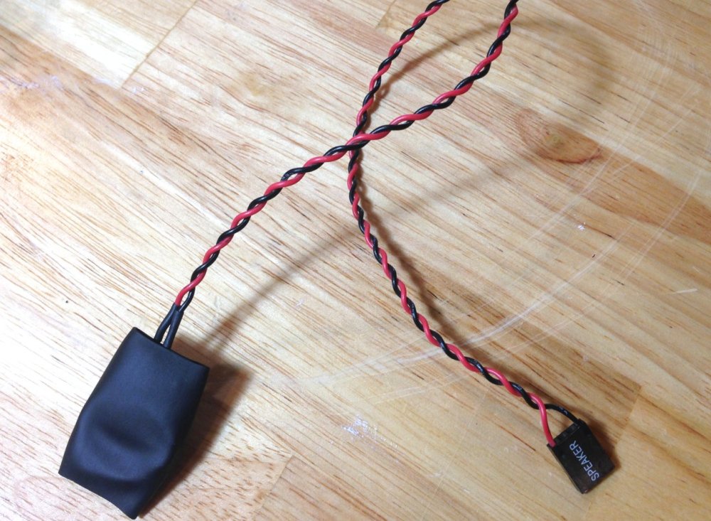
It’s ugly and far from secure, but good enough for a quick test. I simply chopped off a PC speaker header and stripped some of the insulation from the leads. I then taped them on to the respective sides of the battery. This worked and got me about 3.1V across the pins.
I was then able to bypass the barrel battery and powered up the system with a minimal set of components installed. To my relief, it posted just fine and I was able to enter the BIOS and set the correct date and time. I left the system powered off for several hours and found that the time and all BIOS settings were retained the next time it powered up. Clearly 3.1V is plenty for this purpose.
Removing the Barrel Battery
Next up is to remove the barrel battery to prevent future leakage and damage to the board. Obviously my intent is to preserve this wonderful specimen of 1994 engineering and keep it in working condition. To ensure that, the battery has to go.


The site I mentioned earlier provides instructions on desoldering or cutting off the battery. I preferred their easier option of simply clipping the pins using a pair of side-cutters. This proved to be quick work and the glue under the battery was so old that it didn’t even stick any more.
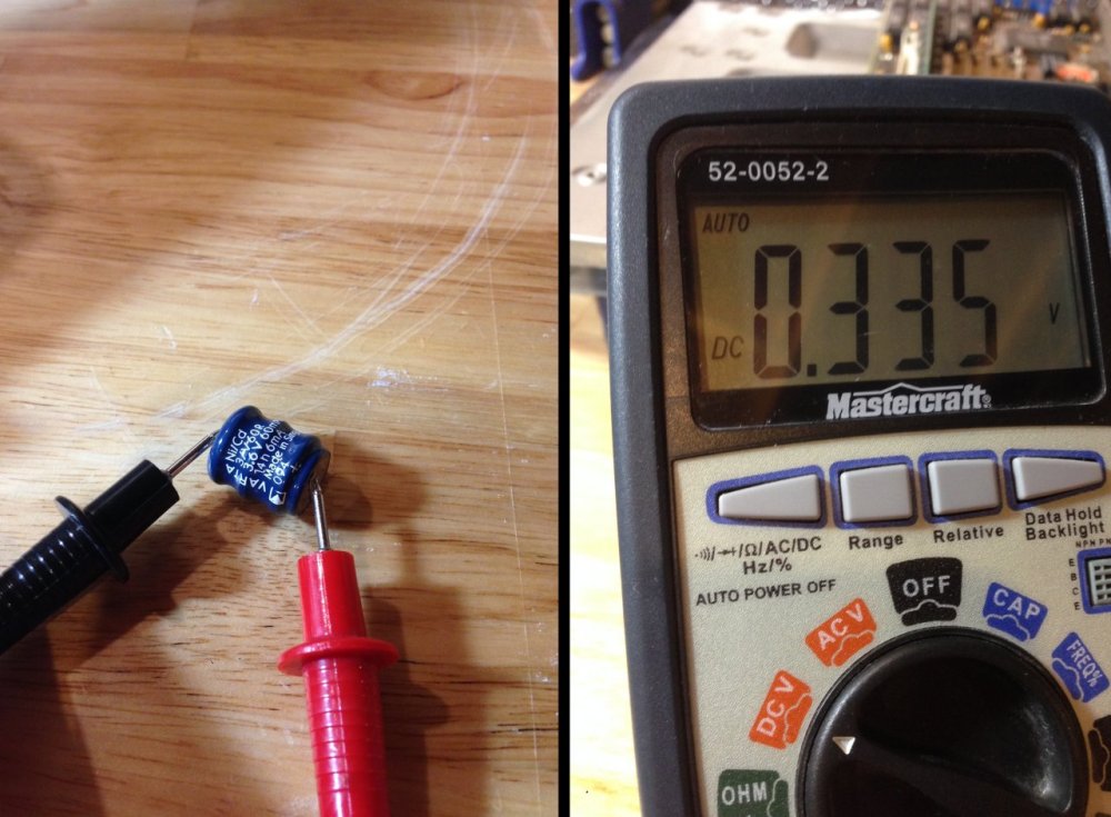
Even after charging for several hours, the barrel battery couldn’t do any better than 0.3V. It had obviously seen better days.
Constructing The Battery Pack
Now that I know the system works just fine with around 3V, it was time to construct a more sturdy battery pack. I liked the idea of sticking with a small CR2032 solution, so that was my first priority. In case I couldn’t make that work, I also bought a small 2xAA pack as well.


I picked these up from a local electronics store for about $2.50 each. The vertical coin cell holder is meant to be soldered to a PCB, but I was hoping to solder it onto the wire leads instead.

My soldering skills leave a lot to be desired, but after practicing a bit I managed to get it on securely. I used some heat-shrink as well to protect the exposed wire and pins. I think it actually turned out pretty well considering.
The only unfortunate thing is that part of the top and bottom of the battery is exposed and could short out if I’m not careful.
Rather than chancing it, I put a wide piece of heat-shrink over the entire battery and warmed it up very briefly. It doesn’t look great, but I was a bit leery to heat up the battery too much. The important thing is that it’s securely on there and provides some insulation. This can easily be removed with a sharp knife should the battery need to be changed out down the road.
<< The 486 Restoration – Part 1 The 486 Restoration – Part 3 >>
What’s Next?
That’s it for this installment. Up next, I’ll be working to get the system booted into DOS for some initial tests. I don’t want to spoil it too much, but I’ve run into many frustrating problems with the Pine PT626A I/O controller card. More on this to come – stay tuned!
Got a retro PC project on the go? I’d like to hear about it! Reach out to me on Twitter (@vswitchzero)
