Synology’s Active Backup for Business is a powerful, license-free backup tool included with many of their higher end “plus” and rackmount NAS units. Here is my latest video taking a look at its integration with VMware vSphere and ESXi. I walk through installation, setup, backup and restore.
In short, it is an excellent tool that provides features you’d expect to see from enterprise “paid” backup solutions. For those with home labs or smaller environments, it makes the value proposition of buying a Synology NAS much more enticing!
The Synology Storage Console for VMware allows storage admins to perform numerous multi-step workflows without ever having to leave the vSphere Client.
I’ve been playing around with Synology’s DS1621+ in my home lab the last couple of weeks and have been thoroughly impressed so far. In my last couple of posts, I got the storage pools created and networking and iSCSI configured. As I was going through the manual setup process, I came across Synology’s Storage Console for VMware plugin. This plugin allows some degree of control of the NAS unit directly from within the vSphere Client and automates some simple workflows. Here are some high level features:
Datastore Creation – Creates a backing LUN, target and the VMFS or NFS datastore in a single workflow.
Datastore Resizing – Resizes the backing LUN and expands the VMFS datastore in a single workflow.
Log Bundles – Allows collection of support log bundles of the Synology NAS from the vSphere Client.
Status Dashboard – Provides NAS status and LUN status information.
Enables application-consistent LUN snapshots.
You can find some more information on the storage console plugin here. As long as you have a supported Synology NAS running DSM 6.2.3 or later and vCenter Server 6.5 U2 or later, you can give it a try.
Installation is very straight-forward. The plugin is installed by deploying a small CentOS based OVA appliance into the environment. During deployment, you’ll be prompted for your vCenter credentials and connection information.
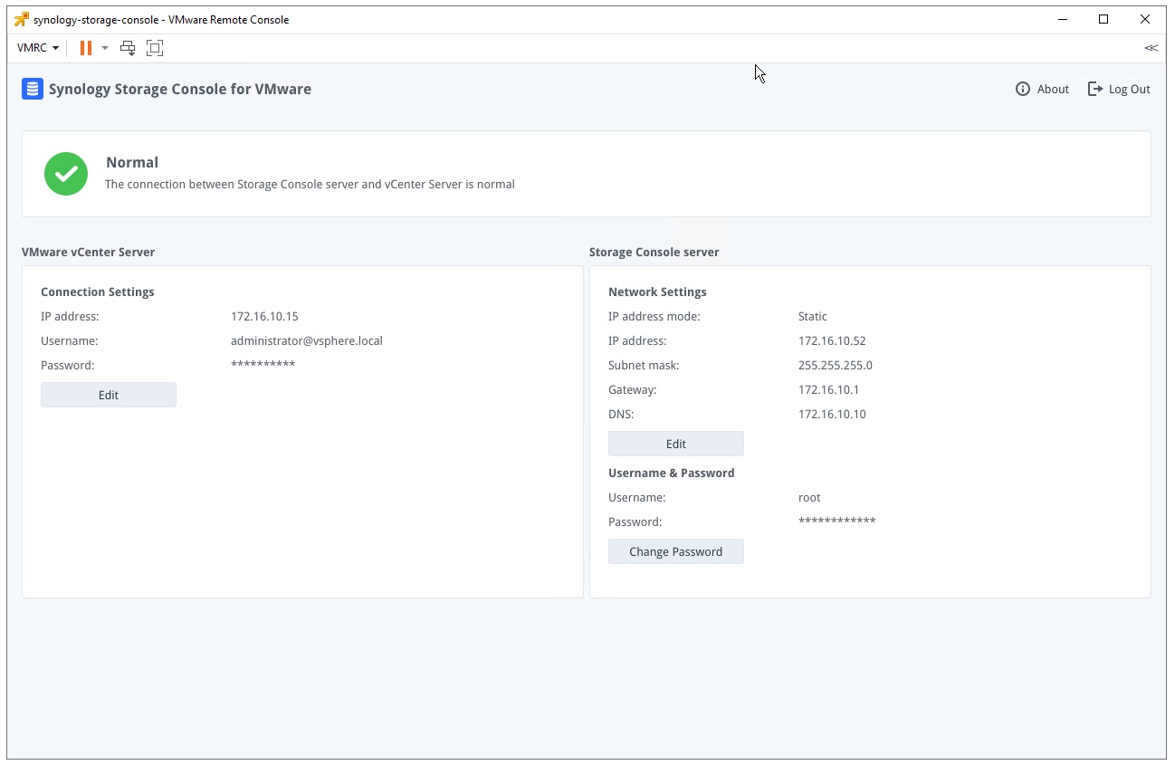
Once the VM powers on, it’ll automatically connect to vCenter Server and install the plugin for you. Opening the VM’s console will greet you with a simple GUI that allows you to change passwords and basic TCP/IP settings.
The console view of the deployed Synology virtual appliance.
The default username and password for this appliance is root/synology, so be sure to change it.
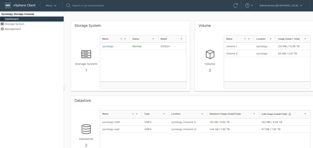
The storage console
After logging out and back into the vSphere Client, the Synology Storage Console plugin should be available via the main menu. You’ll first need to add your NAS unit(s) in the Storage System page. Once done, you’ll be able to use the features the plugin offers. Some simple stats are available from the dashboard section. You can see your storage pools, volumes and available free space. This is useful if you are over-allocating space via thin provisioning.
The Synology DS1621+ is an excellent performer with a 10Gbps NIC. Here’s how to configure networking and iSCSI targets and LUNs for use in a VMware vSphere environment.
In my previous post on the Synology DS1621+, I configured storage pools and volumes. Now that our storage is ready for use, I’ll be configuring iSCSI in my VMware vSphere lab environment.
Network Configuration
A proper network setup is the foundation for a successful iSCSI deployment. I won’t go into too much detail about vSphere network configuration in this post, but here are some general recommendations when it comes to iSCSI:
Use a dedicated VLAN for iSCSI. Do not use it for any other purpose.
Use a dedicated subnet and ensure it is non-routable.
Use a dedicated VMkernel port for iSCSI in the created subnet.
If possible, ensure you have redundant NICs configured on your hosts and storage box.
Use a 9000 MTU if possible (more on this later)
To begin, I’ll be configuring the interface settings on the DS1621+. There are many different ways this can be done, but I only have one spare 10Gbps port currently, so I’ll forgo a proper multipathing configuration and keep things simple. That said, I’ll still configure two interfaces – a single 1Gbps interface for management, and a single 10Gbps interface in a different VLAN for exclusive iSCSI use.
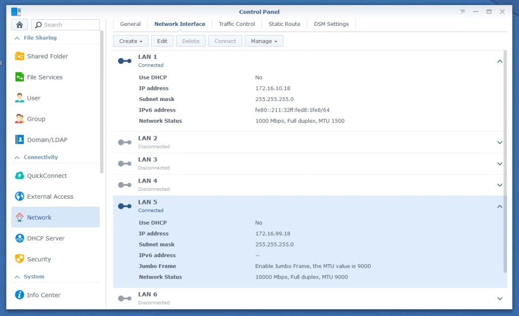
LAN 5 and LAN 6 correspond to the add-in 10Gbps adapter on the DS1621+
LAN 1 is a 1Gbps interface that I have in my management network (172.16.10.0/24). This interface will be used to access the Synology DSM interface and anything else that is non-iSCSI related. In my case, LAN5 and LAN6 are the 10Gbps ports on the DS1621+. The 172.16.99.0/24 network is my iSCSI network and is non-routable. Both interfaces are connected to “access” ports on my physical switch. Since there is no 802.1q VLAN tagging, VLANs are not specified on the DS1621+. I’ll show you how to restrict iSCSI to a specific interface when we configure iSCSI targets later on. Next, we’ll move on to the vSphere networking configuration.
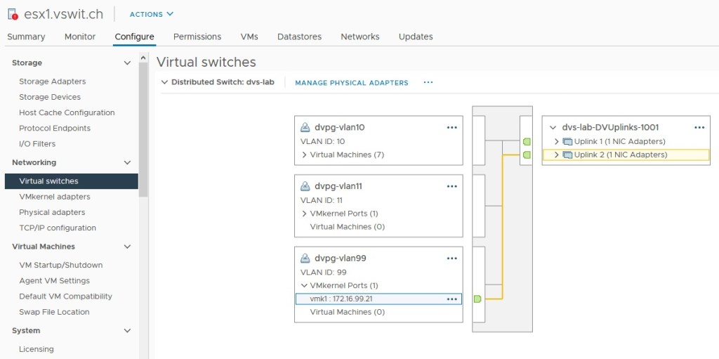
My dvSwitch has two 10Gbps NICs per ESXi host. Everything iSCSI related is in VLAN 99.
Because I already have my TrueNAS box up and running in VLAN 99, my vSwitch and VMkernel ports are already configured correctly for iSCSI in this network. I won’t get too much into vSphere networking configuration today, but I’ll at least show you how I have things configured.
My distributed switch called “dvs-lab” has a dvPortgroup configured with a VLAN ID of 99 configured. Unlike the DS-1621+, each of the 10Gbps NICs here are connected to 802.1q VLAN tagged ports on my switch. I have the default “route based on originating port ID” teaming configured on all the dvPortgroups.
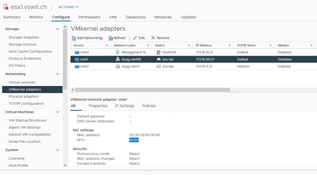
VMkernel vmk1 is connected to the iSCSI VLAN 99 with subnet 172.16.99.0/24.
I also have a dedicated VMkernel port configured for iSCSI in the 172.16.99.0/24 network. In the example above, host esx1 uses 172.16.99.21. Note that I have not configured a gateway for this VMkernel interface because I want this network to remain non-routable. The same is true for my physical layer-3 switch – there are no VIFs attached to the VLAN.
Quick Note on Jumbo Frames
Although there are a lot of varying opinions on jumbo frames out there, I would encourage you to consider using a 9000 MTU for iSCSI. In a tightly controlled, non-routed VLAN like that used for iSCSI in a datacenter, most of the reasons to avoid large frames simply do not apply. Storage traffic tends to be very heavy and the number of frames your ESXi host will need to process with a 1500 MTU will be very high. There is overhead associated with this high packet rate. For example, with 10Gbps networking, a 1GB/s sustained transfer rate is not unreasonable. To put that into perspective, your host would have to process almost 700,000 frames and headers every second with a 1500MTU. With a 9000 MTU, that number would be a little over 100,000 – much easier to handle.
Configuring jumbo frames is outside of the scope of this post, but in my environment, I have jumbo frames configured in the following locations:
Distributed Switch – set to 9000 MTU. This configuration passes to physical vmnics.
VMkernel port for iSCSI – set to 9000 MTU.
Physical switch – Jumbo frames enabled globally.
Synology DS1621+ – Jumbo frames enabled on NET5 interface.
In my previous post, I got the hardware all setup on the DS1621+ test unit that Synology was gracious enough to loan me. Today, I’ll be doing some of the initial storage configuration in preparation for getting iSCSI configured for use in my vSphere lab.
But first, I’ll need to get some flash storage added to the NAS.
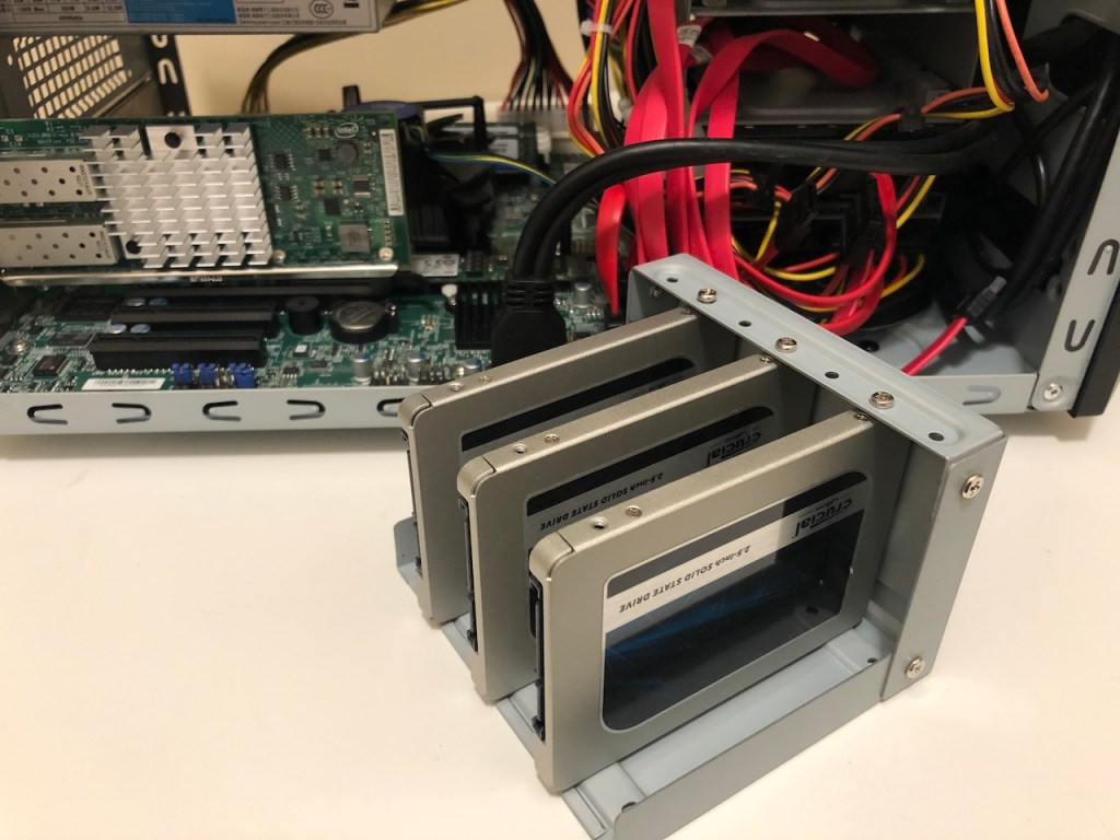
The three donor SSDs coming out of my trusty TrueNAS box.
I’ve got three Crucial MX500 1TB drives that I’ll be removing from my TrueNAS box for testing in the DS1621+. Although they are getting a bit dated, they are still solid performing SATA SSDs. Don’t forget to properly remove your LUNs/Datastores!
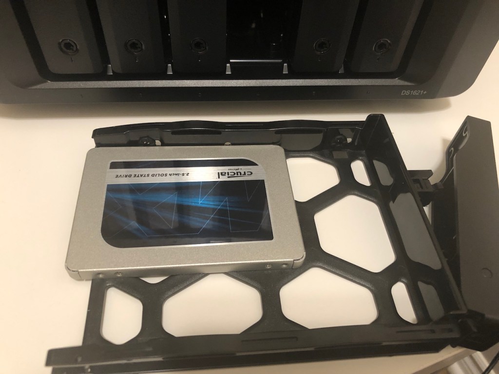
2.5-inch drives look tiny in the DS1621+ drive tray!
Installing the 2.5-inch drives is an easy job. Four small screws attach to the back of each sled and hold the drives in the correct position.
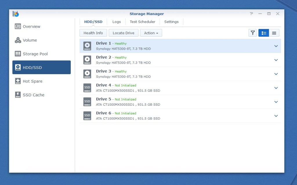
Six drives green and ready to go.
With all six drive bays populated, we’re ready to begin getting the storage prepared for use on the DS1621+.
Creating Storage Pools
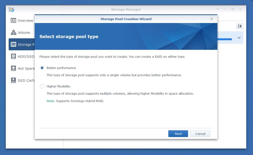
The first thing that needs to be done before you can use the drives is to create one or more storage pools. This is where you group disks and apply a RAID level to them. When clicking the Create button, you’ll be greeted by the storage pool creation wizard.
Classic RAID for best performance or SHR for greater flexibility. Decisions, decisions!
You’ll first be prompted to use classic RAID levels or to use Synology’s Hybrid Raid or SHR. SHR makes the creation of a pool easier, but its best feature is the ability to make use of all disk space when disks of different sizes are in the pool. Traditional RAID levels can waste a lot of space in this type of situation. It is great for beginners, but we’ll stick with the classic RAID-levels.
A new 6-bay AMD Ryzen powered NAS unit from Synology with lots of potential!
My very first commercial NAS box that I bought over 13 years ago was the dual-bay Synology DS207+. At the time, it was the cream of the crop. The hardware was great, but Synology’s very rich software suite was what really set it apart from many of its competitors at the time. The unit served me very well for years in my home network.
Once I got my first VMware home lab setup, I moved away from consumer-grade NAS units and toward more powerful custom-built servers running FreeNAS/TrueNAS. Although awesome for home use, the SoC (system on a chip) ARM-based processors on these old units simply couldn’t handle the I/O requirements for VMs on iSCSI or NFS datastores. Unless you were willing to shell out a lot of dough for an enterprise-grade NAS/SAN, you were stuck building your own. A lot has changed in this market over the last few years. NAS units have gotten much quicker and a reasonably priced unit can now be a very feasible solution for a wide variety of applications – including virtualization. Today, Synology makes a number of multi-bay NAS units with powerful processor options. They have everything from high-performance ARM based units to Xeon-Ds and even AMD Ryzen Embedded options as in the 1621+. Although they still command a premium price, you get way more for your dollar today than you did even just a few years back. When Synology asked if I would be interested in trying out one of their business class “plus” NAS units, I jumped on the opportunity.
Synology was kind enough to send me a review sample including a DS1621+ NAS unit, three of their Synology branded 8TB hard drives and their new E10G21-F2 10Gbps SFP+ NIC. Over the next few weeks, I hope to take a look at this latest generation of multi-bay NAS systems and see how feasible they are for a small to mid-sized business network. I’m also very interested in trying out some of Synology’s included software that is catered towards VMware vSphere. For now, I just wanted to share a quick unboxing and hardware setup post.
Hardware Specifications
The Synology DS1621+ specifications are as follows. You can find the full list on Synology’s DS1621+ page.
CPU Model: AMD Ryzen V1500B (4 cores, 2.2GHz)
Hardware Encryption: Yes, AES-NI
Memory: 1x4GB DDR4 ECC SODIMM (Upgradable to 32GB, 2x16GB)
Power Consumption: 51W (Access), 25W (HDD Hibernation)
Warranty: 3 Years
The specifications for this NAS unit are quite impressive. The one feature that gets most people excited is the embedded AMD Ryzen processor. With AMD’s hugely successful Zen architecture, this is not surprising. AMD has managed some very impressive performance numbers – especially in their 3rd and 4th generation CPUs. Being an embedded part, the Zen V1500B processor is a little different than their desktop processors. From what I can see, it is based on AMD’s first generation Zen architecture so it won’t be quite as potent clock-for-clock as some of AMD’s recent Ryzen CPUs. None the less, with four cores, eight threads and a 2.2GHz clock speed, this is a very capable CPU for a NAS. Best of all, being an embedded part, the total TDP for this processor is only 16W. Having a potent x86-64 CPU under the hood opens up the possibilities for a number of different use cases. Not only should iSCSI storage performance be up to the task, but you could even run virtual machines and many of the more demanding software packages on the NAS unit.
Another great feature is Synology’s inclusion of NVMe. Three and a half inch mechanical drives do still have their place for affordable raw storage capacity, but flash storage is really necessary for good performance. All six drive bays support 2.5 inch SATA SSDs, which is great, but there are now two NVMe slots intended to be used for drive caching as well. Being able to use multiple storage tiers and caching really gives this NAS a lot of performance potential.
Unboxing
Without further ado, let’s check out the DS1621+ and the other goodies Synology sent over.
Synology included three 8TB drives and an SFP+ NIC along with the DS1621+
Synology moved away from flashy packaging years back. I like the subtle cardboard packaging because it lets the quality of the product speak for itself.
The size of the box makes the NAS unit feel larger than it actually is. There is ample protection from shipping damage with foam protecting the unit from all sides. The NAS itself is wrapped in plastic to keep dust out.
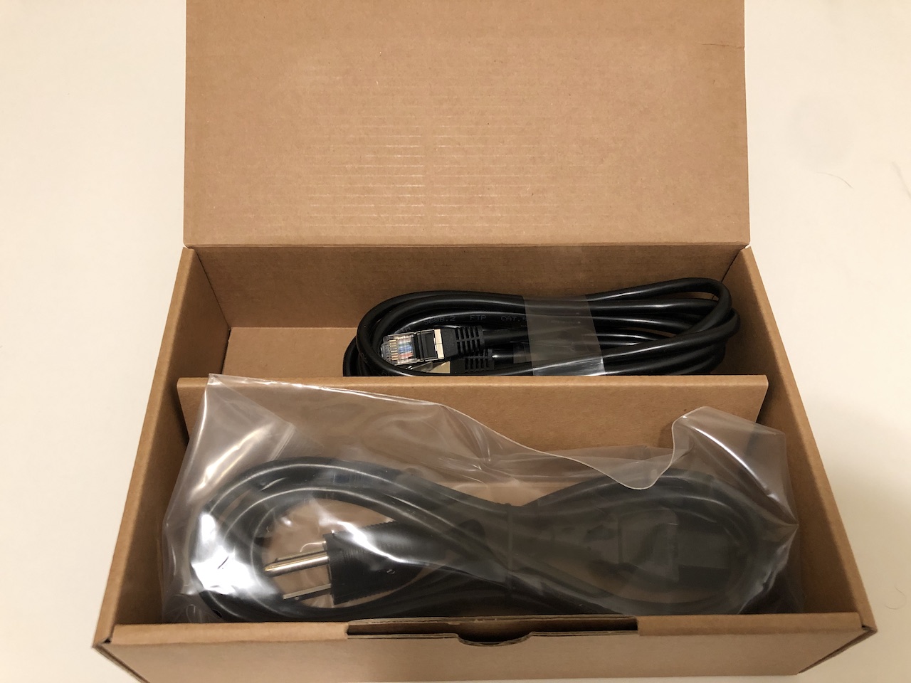
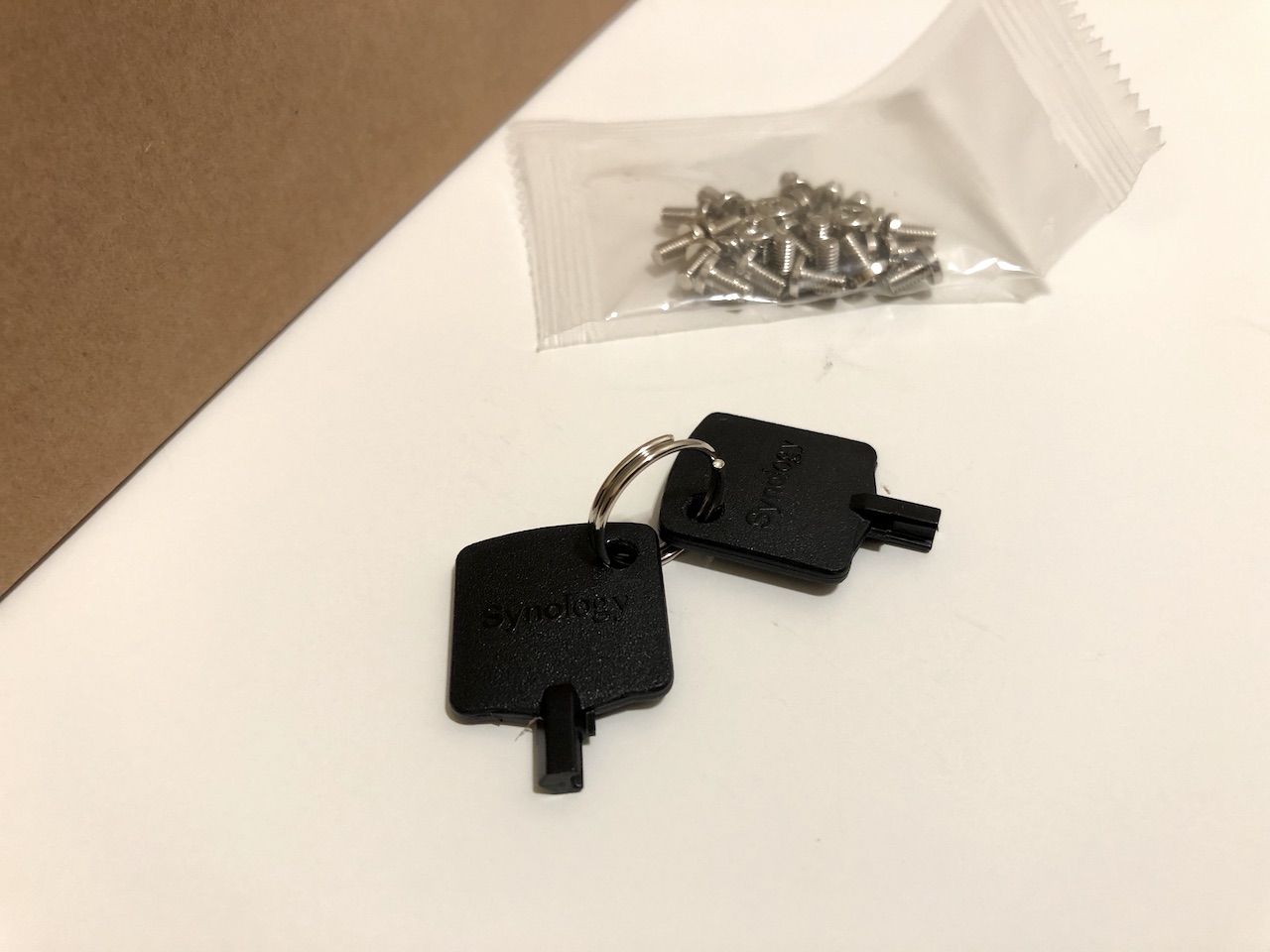
A small cardboard box includes a pair of high quality ethernet cables and a standard power cable. A small bag of screws and the drive bay keys are also contained within. From what I can see, the screws are only needed for mounting 2.5-inch drives.
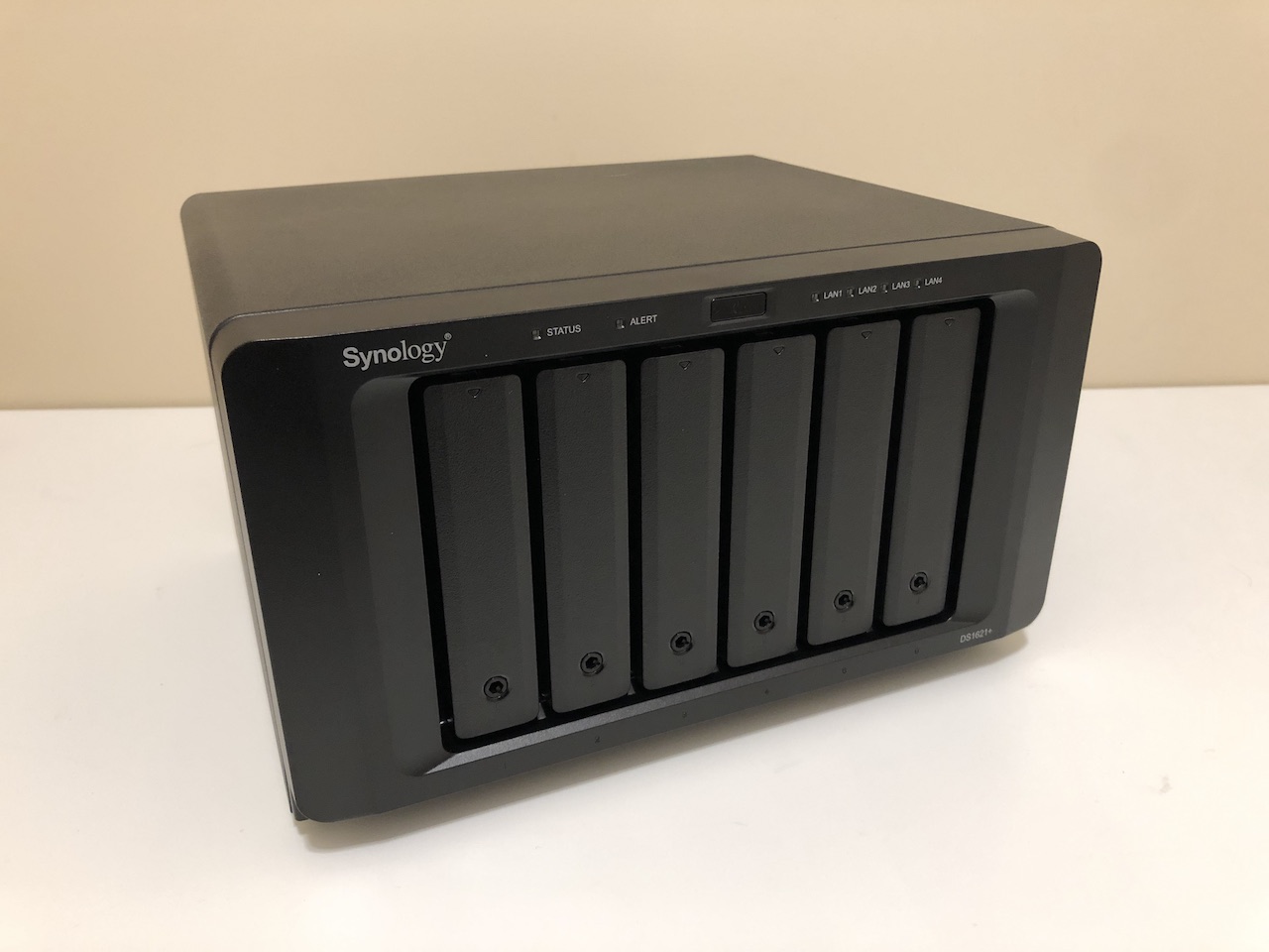
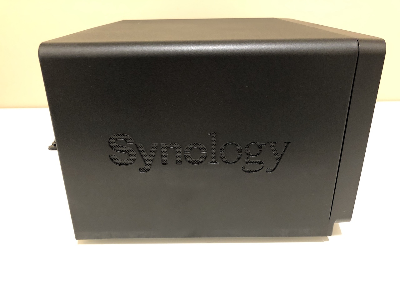
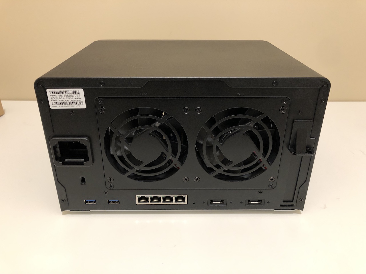
The unit itself has a heavy, high quality feel to it. The outer shell and back panel are metal and only the front panel and drive bays are constructed of plastic. Six hotswap SATA drive bays are accessible from the front of the unit. Two 92mm fans dominate the back and line up perfectly behind all six drive bays and should provide good directed airflow.
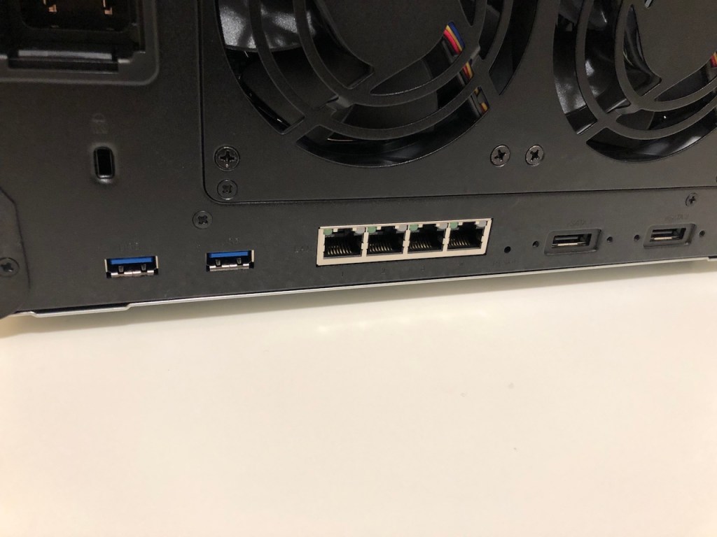
The DS1621+ includes plenty of I/O out of the box, including four GbE ports.
There are two USB3 ports at the rear (and one at the front) as well as four 1GbE NICs and a pair of eSATA connectors. The eSATA ports can be used for Synology’s expansion units. With two DX517s, you could have up to 16 drives in total.
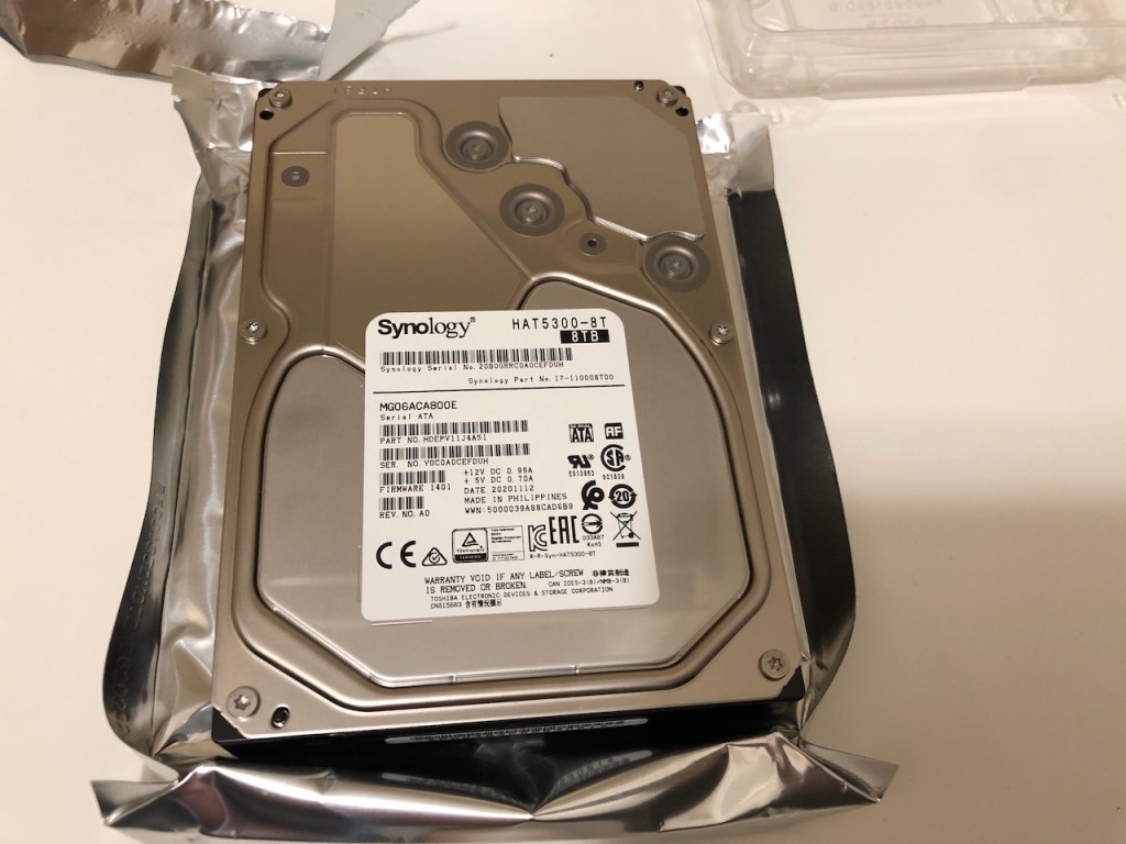
The Synology HAT5200-8T 7200RPM hard drive.
Synology was kind enough to include three of their self-branded 8TB HAT5300 mechanical drives with the NAS unit. From what I can see, these are manufactured by Toshiba and are 7200RPM models. Synology supports a large number of mechanical drives from a variety of manufacturers, but supplying their own removes the guess work that customers need to do and guarantees 100% compatibility.
Synology’s E10G21-F2 SFP+ 10Gbps NIC
Since I plan on using this NAS in my VMware home lab, 10GbE networking will be essential. Synology provided me with their brand new E10G21-F2 SFP+ card. Synology supports a pretty long list of 10Gbps NICs on some of their older NAS units, but the list is short for the DS1621+ at this time. I suspect they are still testing cards for compatibility as this NAS is still quite new. Similar to their branded HDDs, going with a Synology branded NIC ensures 100% compatibility. Synology sells 10Gbase-T models as well if you aren’t using SFP+ DACs or optics.
The perfect Raspberry Pi 4 case to use for VMware’s ESXi on Arm fling. It doesn’t get much better than this.
I’m a bit late to the party, but I finally picked up a Raspberry Pi 4B 8GB board to use with VMware’s new ESXi on Arm technical preview. I initially tested it without a case, and a small USB 3.1 flash drive. It wasn’t long until I realized the system was pretty much unusable without decently performing storage attached. It did a lot better with an external USB drive I had lying around, but I didn’t like the mess of cables and having devices larger than the Raspberry Pi attached just seemed wrong.
After looking around for a suitable case, I was immediately drawn to Argon Forty’s new Argon One M.2 case.
I had seen the original Argon One, which ticked many of the right boxes, but this one adds one feature I really wanted – built in storage. As the name implies, there is an M.2 SATA storage adapter that is enclosed within the case. If you have already bought an Argon One, you can buy the M.2 bottom kit as a standalone option to convert yours as well!
The case parts after unboxing. Everything has a high quality feel to it.
Along with the Argon One M.2, I purchased their 18W 5.25V power supply, which came highly recommended. I also picked up a very inexpensive 240GB M.2 SATA drive on Amazon made by Asseno. The case itself is comprised of a top and bottom shell with attached circuit boards. An additional board is included that attaches to the Pi as well as a USB to USB bridge.
Raspberry Pi 4B 8GB with side board installed.
A small circuit board attaches to the ports at the side of the Raspberry Pi and redirects them toward the rear. I absolutely love this feature as the default placement of ports on the Pi can make wiring a bit of a mess. As an added bonus, the adapter converts the two micro-HDMI ports to full size HDMI connectors. The larger connectors are a much more popular connector type, and this could save you from having to buy a micro-HDMI cable or adapter. You’ll also notice that the USB Type C power connector is not attached and left unused. This is because power input is provided through the pin bank once the top of the case is attached.
Windows server licenses aren’t cheap so why not pair your AD domain controller with a Linux BIND9 secondary instead? Find out how!
Having a backup for your Windows Active Directory DNS services is always a good idea. Larger organizations would probably have a backup domain controller providing secondary DNS duties, but this may not be feasible for small shops or home labs. Windows server licenses aren’t cheap so why not pair your AD domain controller with a Linux BIND9 secondary instead?
I ran a home lab with a single DNS server for years, but I got into a few situations where it became problematic. To conserve power, I shut down the majority of my home lab, including the hosts that run my Active Directory VM. I wanted to maintain DNS functionality for the limited number of VMs that stay powered up 24/7. Having a functional secondary was the answer.
What is a DNS Secondary?
A DNS secondary is a DNS server containing read-only copies of DNS zones received from a DNS primary. All of your “A”, “MX” and other records are configured in the zones of the primary and then are sent to the secondary using “zone transfers”. In practice, the secondary zones should always be identical to that of the primary. If the primary goes down, clients will still be able to resolve DNS queries via the secondary. Obviously, in order for this to work, all of your client devices and VMs will need to have both DNS servers defined in their TCP/IP configuration.
Configuring Your Windows DNS Server
Before you can do zone transfers to your new secondary, some configuration will be required on your Active Directory DNS server. I’m using Windows Sever 2018, but this should be the same for 2012/2016 and even 2008 if I’m not mistaken.
Before changing any configuration, you’ll need to create a standard “A” record for your secondary DNS server in your forward lookup zone. In my case, it is ns2.vswit.ch with an IP of 172.16.10.11:
Next, from the DNS snap-in, right click on your DNS server and go to Properties and click the Advanced tab.
TLDR: Modify your power plan to ensure your VM isn’t going to sleep!
I had recently deployed a new Windows 10 based VM that would serve as an RDP jump box to access lab resources. Initially RDP worked fine, but I noticed that after a while I couldn’t connect any more. The only way to rouse it from this state was to open a direct console window from the vSphere Client, or to reboot the VM.
The exact error message from the Remote Desktop for Mac window is:
“We couldn’t connect to the remote PC. Make sure the PC is turned on and connected to the network, and that remote access is enabled.
Error code: 0x204”
In addition to the 0x204 error, I also saw “Error code: 0x4” numerous times as well.
The two error codes I kept getting (0x204 and 0x4) were not helpful and just led me on a wild goose chase. These codes were only reported on the Mac RDP client and Windows was more generic:
Clearly the message “Make sure the PC is turned on” garnered no attention from a seasoned IT professional like me, but in the end turned out to be relevant. The issue was that the Windows 10 VM was going to sleep.
I only noticed this when I saw a blacked-out screen in the console preview and the lack of a hostname or IP address listed. This tells me that VMware tools hasn’t checked in for a period of time.
I’m not sure if an incoming RDP connection attempt would wake a physical machine in this state, but sleep isn’t very beneficial to a VM. I simply modified the power settings to prevent sleep and hibernation and the issue hasn’t happened again.
Windows Server varieties don’t behave this way, but because Windows 10 is primarily intended for bare-metal laptop and desktop use cases, power saving features are enabled by default.
This is a pretty basic problem, but I thought I’d do a post just in case it helps someone else who overlooked the obvious like I did and instead tried chasing up hexadecimal error codes 🙂
I noticed that my Windows 10 VM kept becoming inaccessible after shutting down and powering up my lab. As part of the power down process, I was cutting power to the MikroTik CRS309 switch, which is the default gateway for the VMs in VLAN 1. After opening a console to the Windows VM I discovered that the network discovery feature was detecting a new network and prompting whether it was trusted. This discovery is based upon the MAC address of the default gateway – sure enough it seemed to be changing after each power up of the CRS309.
After doing some research it seems that this is expected behaviour. The bridge MAC is auto-selected based on one of the bridge ports at boot-up. Because of this, there is a good chance the MAC will change after each boot. If I left my switch up 24/7, this wouldn’t be a problem, but since I don’t, I need keep things consistent.
The MikroTik wiki mentions two options – admin-mac and auto-mac. These two can be used to force the bridge to use a static MAC address. I just selected the current auto-generated MAC to use for this purpose.
You can get the current bridge configuration using the following command:
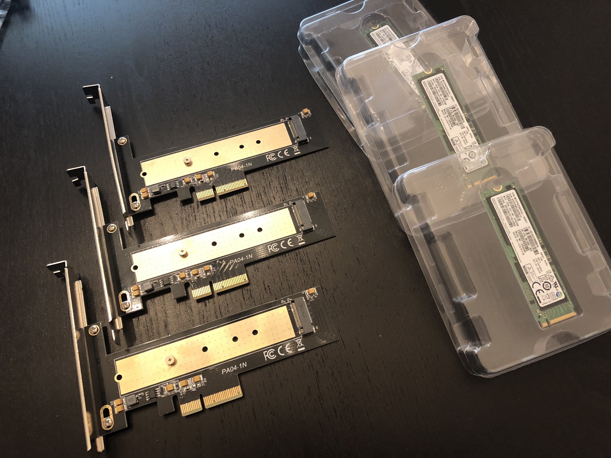
I recently deployed an all-NVMe based vSAN configuration in my home lab. I’ll be posting more information on my setup soon, but I decided to use OEM Samsung based SSDs. I’ve got 256GB SM961 MLC based drives for my cache tier, and larger 1TB enterprise-grade PM953s for capacity. These drives are plenty quick for vSAN and can be had for great prices on eBay if you know where to look.
The Samsung Polaris based SM961 is similar to the 960 Pro and well suited for vSAN caching.
Being OEM drives, they don’t have any heatsinks and are pretty bare. As I started running some performance tests using synthetic tools like Crystal Disk Mark and ATTO, I began to see instability. My guest running the test would completely hang after a few minutes of testing and I’d be forced to reboot the ESXi host to recover.
Looking through the logs, it became clear what had happened:
2019-08-16T15:43:26.083Z cpu0:2341677)nvme:AsyncEventReportComplete:3050:Smart health event: Temperature above threshold
2019-08-16T15:43:26.087Z cpu9:2097671)nvme:NvmeExc_ExceptionHandlerTask:317:Critical warnings detected in smart log [2], failing controller
2019-08-16T15:43:26.087Z cpu9:2097671)nvme:NvmeExc_RegisterForEvents:370:Async event registration requested while controller is in Health Degraded state.
One of my nvme drives had overheated! The second time I tried the test, I watched more closely.
Sure enough, it wasn’t the older PM953s overheating, but the newer Polaris based SM961 cache drives. As soon as the heavy writes started, the drive’s temperature steadily increased until it approached 70’C. The moment it hit 70, the guest hung. Looking more closely in ESXi, I could see that the drive completely disappeared. I.e. it was no longer listed as a NVMe device or HBA in the system. It appears that this is safety measure to stop the controller from cooking itself to the point of permanent damage. Since I had no idea it was running so hot, I’d say I’m thankful for this feature – but none the less, I’d have to figure out some way to keep these drives cooler.
ESXi has a limited implementation of SMART monitoring and can pull a few specific metrics. Thankfully, drive temperature is one of them. First, I needed to get the t10 identifier for my nvme drives:
[root@esx-e1:~] esxcli storage core device list |grep SAMSUNG
t10.NVMe____SAMSUNG_MZVPW256HEGL2D000H1______________6628B171C9382499
Display Name: Local NVMe Disk (t10.NVMe____SAMSUNG_MZVPW256HEGL2D000H1______________6628B171C9382499)
Devfs Path: /vmfs/devices/disks/t10.NVMe____SAMSUNG_MZVPW256HEGL2D000H1______________6628B171C9382499
Model: SAMSUNG MZVPW256
t10.NVMe____SAMSUNG_MZ1LV960HCJH2D000MU______________1505216B24382888
Display Name: Local NVMe Disk (t10.NVMe____SAMSUNG_MZ1LV960HCJH2D000MU______________1505216B24382888)
Devfs Path: /vmfs/devices/disks/t10.NVMe____SAMSUNG_MZ1LV960HCJH2D000MU______________1505216B24382888
Model: SAMSUNG MZ1LV960
Running a four second refresh interval using ‘watch’ is a useful way to monitor the drive under stress.
[root@esx-e1:~] watch -n 4 "esxcli storage core device smart get -d t10.NVMe____SAMSUNG_MZVPW256HEGL2D000H1______________6628B171C9382499"
Parameter Value Threshold Worst
---------------------------- ----- --------- -----
Health Status OK N/A N/A
Media Wearout Indicator N/A N/A N/A
Write Error Count N/A N/A N/A
Read Error Count N/A N/A N/A
Power-on Hours 974 N/A N/A
Power Cycle Count 62 N/A N/A
Reallocated Sector Count 0 95 N/A
Raw Read Error Rate N/A N/A N/A
Drive Temperature 35 70 N/A
Driver Rated Max Temperature N/A N/A N/A
Write Sectors TOT Count N/A N/A N/A
Read Sectors TOT Count N/A N/A N/A
Initial Bad Block Count N/A N/A N/A
As you can see, the maximum temperature is listed as 70’C. This isn’t a suggestion as I’ve come to learn the hard way.
To get things cooler I decided to move my fans around in my Antec VSK4000 cases. My lab is geared toward silence more than cooling so the airflow near the PCIe slots is pretty poor. I’ve now got a 120mm fan on the side-panel cooling the slots directly. This benefits my Solarflare 10Gbps NICs as well, which can get quite toasty. This helped significantly, but if I leave a synthetic test running long enough, it will eventually get to 70’C again. Clearly, I’ll need to add passive heatsinks to the SM961s if I want to keep them cool in these systems.
Realistically, it’s only synthetic and very heavy write tests that seem to get the temperature climbing to those levels. It’s unlikely that day-to-day use would cause a problem. None the less, I’m going to look into heatsinks for the drives. They can be had for $5-10 on Amazon, so it seems like a small investment for some extra peace of mind.
The morale of the story – keep an eye on your NVMe controller temps!