This will be the first of several posts on configuring the new MikroTik CRS309-1G-8S+IN for use in a VMware home lab. Today’s first post will introduce MikroTik’s RouterOS and will focus on VLAN trunking. Please note that although this was written for the CRS309, this should be applicable to all CRS3xx series switches, including the popular CRS317.
RouterOS vs SwOS
MikroTik’s RouterOS firmware that comes pre-loaded on the switch is very feature rich with loads of L3 functionality. It has everything from BGP/OSPF, to firewalling, NAT, DHCP services – you name it. It’s a multi-purpose firmware that was originally created for MikroTik’s routers. Today, it works with many of their other products, including switches, and wireless devices. Because of this, it feels more like router firmware adapted for use with switches as opposed to something designed especially for them. Configuring RouterOS on the CRS309/CRS317 can be challenging and there is a learning curve to overcome – even for those with a lot of networking experience. Things get easier when you learn the terminology and understand what does and does not apply to a switch within RouterOS.
The CRS309 also includes ‘SwOS’ – a straight-forward L2 firmware that is designed especially for their switches. I found SwOS’s UI to be very intuitive and a lot more like what I’d expect to see on a switch. If you are not looking to use any of the advanced L3 features that RouterOS offers, I’d highly recommend using SwOS instead. There is no need to flash back and forth from RouterOS to SwOS and vice-versa. Both firmware packages coexist in the flash memory and you can easily switch back and forth as required.
Although SwOS could suffice for my needs in the home lab, I’m not one to shy away from a challenge and really want to be able to take advantage of some of the L3 features. If I could get them to work, I could potentially retire one or two virtual machines that I currently use for routing and firewalling.
802.1q VLAN Trunking
One of the first things I tried to do with the CRS309 was get a bunch of VLANs created and all the interfaces configured as 802.1q VLAN trunk ports. This is probably the most common VMware home lab requirement with 10Gbps networking. Each host will have a limited number of interfaces, so VLAN trunks are critical to separate out the various services.
When you get into the RouterOS WebFig interface, you’ll find several places where VLANs can be configured. My first attempt was under ‘Switch’ and ‘VLANs’ – sounds logical enough:
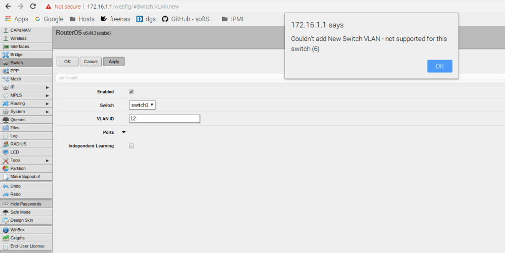
But clearly this doesn’t work. There is also a section for VLANs under ‘Interfaces’, but this is for VLAN interface creation, which I’ll get into later. One of the first things to keep in mind with RouterOS is that a lot of the configuration relating to the switch – including VLAN configuration – is done in the ‘Bridge’ section – not the Switch section.
From the CRS3xx series manual:
“Since RouterOS v6.41 bridges provide VLAN aware Layer2 forwarding and VLAN tag modifications within the bridge. This set of features makes bridge operation more like a traditional Ethernet switch and allows to overcome Spanning Tree compatibility issues compared to configuration when tunnel-like VLAN interfaces are bridged..”
Another important thing to remember is that any VLAN related configuration you do in the bridge does not come into effect until an option called vlan-filtering is set to ‘yes’ for the bridge itself.
Configuring VLAN Trunking
One of the challenges I had when configuring VLANs on the CRS309 was that I kept losing access to the management UI as I attempted to make changes. Rather than relying on the UI, I decided to make all changes using the serial console and the CLI. That way, I wouldn’t have to worry about losing access to the switch. I also thought it would be good to start completely from scratch for educational purposes.
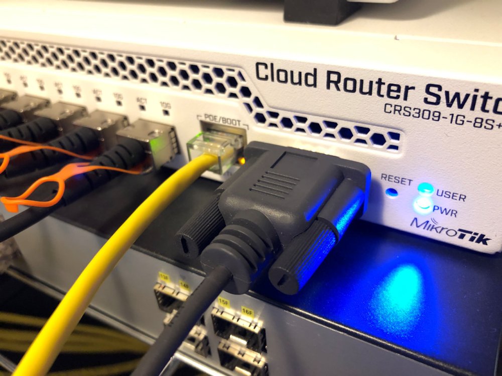
Important Note: Don’t follow my instructions below unless you can do so from the serial console. You’ll lock yourself out of the switch if you try this from an SSH prompt. If you don’t already have one, I’d highly recommend buying an 8-pin serial passthrough cable and/or a USB-to-Serial adapter.
To begin, I reset the switch back to factory defaults.
[admin@MikroTik] > /system reset-configuration
Dangerous! Reset anyway? [y/N]:
y
system configuration will be reset
Once the switch rebooted, I answered ‘r’ to prevent the firmware from loading a bunch of preconfigured options so that I could truly start from scratch. Don’t do this unless you are using the serial console as there will be no IP address assigned to the switch.
The following default configuration has been installed on your router:
-------------------------------------------------------------------------------
Switch mode:
 * all interfaces switched;
LAN Configuration:
-------------------------------------------------------------------------------
You can type "v" to see the exact commands that are used to add and remove
this default configuration, or you can view them later with
'/system default-configuration print' command.
To remove this default configuration type "r" or hit any other key to continue.
If you are connected using the above IP and you remove it, you will be disconnected.
Answering ‘r’ prevents the creation of a default bridge and management IP among other things. First, I’ll start by adding all interfaces to a new bridge that I’ll call ‘bridge1’:
[admin@MikroTik] > /interface bridge add name=bridge1 vlan-filtering=yes
Notice that I also set vlan-filtering to ‘yes’ so that all of the VLAN functionality would be enabled. You can see detail on the bridge by using the ‘print’ command as shown below:
[admin@MikroTik] > /interface bridge print
Flags: X - disabled, R - running
 0 R name="bridge1" mtu=auto actual-mtu=1500 l2mtu=65535 arp=enabled
     arp-timeout=auto mac-address=92:75:6B:06:D8:D9 protocol-mode=rstp
     fast-forward=yes igmp-snooping=no auto-mac=yes ageing-time=5m
     priority=0x8000 max-message-age=20s forward-delay=15s
     transmit-hold-count=6 vlan-filtering=yes ether-type=0x8100 pvid=1
     frame-types=admit-all ingress-filtering=no dhcp-snooping=no
I’m leaving MTU at 1500 for now, but will discuss jumbo frame configuration in a future post. Now that we have the bridge created, we’ll need to add switch ports to it. As you can see below, there were no ports added by default:
[admin@MikroTik] > /interface bridge port print
Flags: X - disabled, I - inactive, D - dynamic, H - hw-offload
 #     INTERFACE     BRIDGE        HW  PVID PR  PATH-COST INTERNA...    HORIZON
Next, I’ll add all of the switch interfaces to the bridge:
[admin@MikroTik] > /interface bridge port add bridge=bridge1 interface=all hw=yes
[admin@MikroTik] > /interface bridge port print
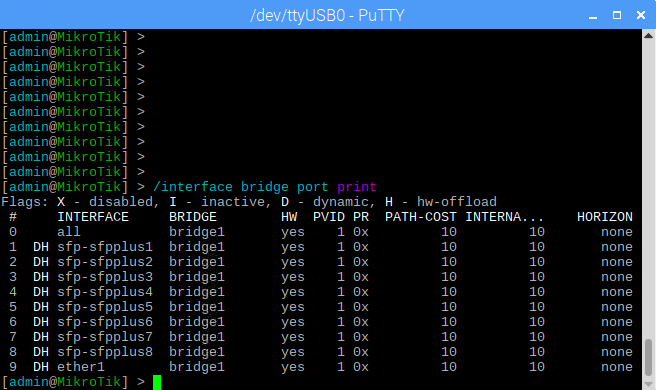
Notice that I specified hw=yes. This is important because it tells RouterOS that the ports are handled by the ASIC of the Marvell switching chip. The ARM based CPU won’t be used for basic frame forwarding allowing for much better L2 switching performance. Notice that by default, all of the ports added to the bridge have a PVID (default VLAN) ID of 1.
To view the current VLAN table of the bridge, you can run the following command:
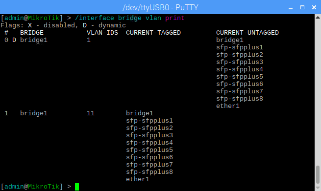
[admin@MikroTik] > /interface bridge vlan print
By default, all ports including bridge1 will be sitting in VLAN1 and are untagged. A ‘D’ flag indicates that this table entry was dynamically created.
Now that all the switch ports are added to the bridge, I’ll start configuring the VLANs. I got stuck at this spot for a while because I was trying to add all VLANs to all ports in a single command. The switch accepts this, but it doesn’t seem to work properly. You should add them one at a time instead.
For my lab, I’ll be adding VLANs 1, 11, 76, 98, 2005 and 3100. I want all SFP+ ports, as well as the 1Gbps copper interface to have all 6 VLANs trunked. To accomplish this, the ports will be added as ‘tagged’ ports to each VLAN. In addition to the SFP+ and copper ports, it’s critical that you also add the bridge itself as a tagged port to each VLAN. If you don’t you won’t be able to access any VLAN IP interfaces or L3 features provided by the CPU on those VLANs.
I’ll begin by configuring VLAN 11 as an example:
[admin@MikroTik] > /interface bridge vlan add vlan-ids=11 bridge=bridge1 tagged=sfp-sfpplus1,sfp-sfpplus2,sfp-sfpplus3,sfp-sfpplus4,sfp-sfpplus5,sfp-sfpplus6,sfp-sfpplus7,sfp-sfpplus8,ether1,bridge1
Now we can see that there is another entry in the VLAN table at position ‘1’:
I’ll then continue by adding the remaining VLANs:
[admin@MikroTik] > /interface bridge vlan add vlan-ids=76 bridge=bridge1 tagged=sfp-sfpplus1,sfp-sfpplus2,sfp-sfpplus3,sfp-sfpplus4,sfp-sfpplus5,sfp-sfpplus6,sfp-sfpplus7,sfp-sfpplus8,ether1,bridge1
[admin@MikroTik] > /interface bridge vlan add vlan-ids=98 bridge=bridge1 tagged=sfp-sfpplus1,sfp-sfpplus2,sfp-sfpplus3,sfp-sfpplus4,sfp-sfpplus5,sfp-sfpplus6,sfp-sfpplus7,sfp-sfpplus8,ether1,bridge1
[admin@MikroTik] > /interface bridge vlan add vlan-ids=2005 bridge=bridge1 tagged=sfp-sfpplus1,sfp-sfpplus2,sfp-sfpplus3,sfp-sfpplus4,sfp-sfpplus5,sfp-sfpplus6,sfp-sfpplus7,sfp-sfpplus8,ether1,bridge1
[admin@MikroTik] > /interface bridge vlan add vlan-ids=3100 bridge=bridge1 tagged=sfp-sfpplus1,sfp-sfpplus2,sfp-sfpplus3,sfp-sfpplus4,sfp-sfpplus5,sfp-sfpplus6,sfp-sfpplus7,sfp-sfpplus8,ether1,bridge1
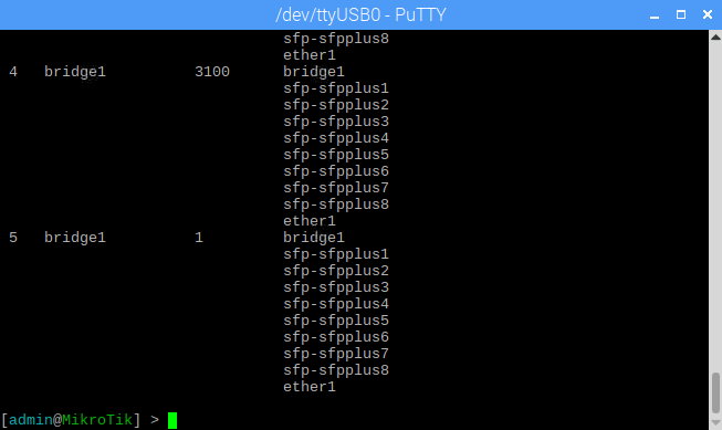
At this point, 802.1Q trunking should function correctly on all of the ports. The only exception is the default VLAN 1, which has all ports still set to ‘untagged’. We can run a similar ‘add’ command for VLAN 1 to get all the ports tagged:
[admin@MikroTik] > /interface bridge vlan add vlan-ids=1 bridge=bridge1 tagged=sfp-sfpplus1,sfp-sfpplus2,sfp-sfpplus3,sfp-sfpplus4,sfp-sfpplus5,sfp-sfpplus6,sfp-sfpplus7,sfp-sfpplus8,ether1,bridge1
Now we can see VLAN 1 set for all ports as ‘tagged’. Note that it moved down to the last position in the VLAN table when we did this:
What I did above assumes you want every single port, including the copper interface tagging all VLANs. If you had a port you wanted to leave untagged, you could modify the above commands I used slightly to achieve this. For example, if you had sfp-sfpplus8 connected to a server in VLAN 98 and didn’t want to trunk VLANs to this port you could do the following:
[admin@MikroTik] > /interface bridge vlan add vlan-ids=98 bridge=bridge1 tagged=sfp-sfpplus1,sfp-sfpplus2,sfp-sfpplus3,sfp-sfpplus4,sfp-sfpplus5,sfp-sfpplus6,sfp-sfpplus7,ether1,bridge1 untagged=sfp-sfpplus8
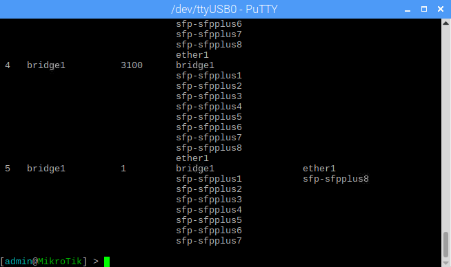
If you want to make changes to one of the VLANs you already added, you can use the ‘set’ instead of ‘add’ command. Let’s say we wanted the copper ‘ether1’ port and sfp-sfpplus8 to be untagged for VLAN 1 instead of tagged. Since VLAN 1 already exists in the table, we’d use ‘set’ instead of ‘add’:
[admin@MikroTik] > /interface bridge vlan set vlan-ids=1 bridge=bridge1 tagged=sfp-sfpplus1,sfp-sfpplus2,sfp-sfpplus3,sfp-sfpplus4,sfp-sfpplus5,sfp-sfpplus6,sfp-sfpplus7,bridge1 untagged=ether1
numbers: 5
Notice that we’re prompted for ‘numbers’ after we run the set command. This is asking for the position in the VLAN table that we wanted to modify. In my case, VLAN 1 was at table position 5.
You can also remove a VLAN from the table by using the ‘remove’ command. To get rid of VLAN 3100, I could run the following:
[admin@MikroTik] > /interface bridge vlan remove 4
Again, the number 4 here corresponds to VLAN 3100’s position in the VLAN table.
Management IP
So now that the VLANs are configured and working from an L2 perspective, we’ll need to get a management IP configured on the switch so that it can be managed from the UI. Normally, you’d just set an ip address on the bridge itself, but because we’ve tagged the bridge1 interface this doesn’t seem to work. Instead, I’ll create a VLAN interface in VLAN 1 and give it an IP address.
The first step is to create a VLAN interface. I called it “INT_VLAN1” and attached it to the bridge1 interface.
[admin@MikroTik] > /interface vlan add interface=bridge1 name=INT_VLAN1 vlan-id=1
[admin@MikroTik] > /interface vlan print
Flags: X - disabled, R - running
 #   NAME                  MTU ARP             VLAN-ID INTERFACE
 0 R INT_VLAN1            1500 enabled               1 bridge1
Once that is created, I just need to give it an IP address:
[admin@MikroTik] > /ip address add interface=INT_VLAN1 address=172.16.1.1/24
[admin@MikroTik] > /ip address print
Flags: X - disabled, I - invalid, D - dynamic
 #   ADDRESS            NETWORK         INTERFACE
 0   172.16.1.1/24      172.16.1.0      INT_VLAN1
As soon as I did that, I could access 172.16.1.1 from all VMs and machines in VLAN 1. I was then able to use it to log into the web UI of the switch:
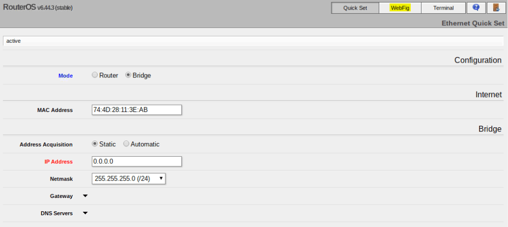
At your first login you’ll be greeted by the Quick Set page. Don’t give the switch an IP here. It’ll just create a bridge and set that IP there. We don’t need to do this since we have a VLAN interface and IP set already. Just click WebFig to get to the UI.
Once you are there, you can see a lot of what we did in the CLI:
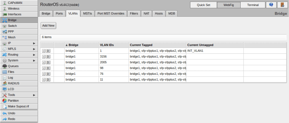
You’ll notice that the VLAN interface we created is listed as ‘untagged’ in the table. Don’t worry about this – because it was created with a VLAN ID specified, it’ll always be accessible by everything in that VLAN.
Conclusion
At this point, you have functional VLANs, all ports are trunking and the UI can be accessed again using the VLAN interface and IP that we configured. Best of all, we did this with RouterOS and can begin to configure a whole suite of cool L3 features.
Stay tuned for some more posts on configuring the Mikrotik CRS309 and RouterOS. In the next post, I’ll get Inter-VLAN routing up between all the VLANs we configured.

Mike,
Thanks for the write up!
Regarding: “[…] if you had sfp-sfpplus8 connected to a server in VLAN 98 and didn’t want to trunk VLANs to this port […]”. I have a similar requirement and found that I had to do some changes to the bridge port to make this work ( interface bridge port add bridge=bridge1 interface=sfp-sfpplus8 hw=yes pvid=98 ).
Cheerio,
Mike
Thanks for sharing, Michael!
This is fantastic! took longer to find my null modem cable than it did to configure this properly. I spent 3 days learning all the wrong ways to create the trunk before finding giving up and asking google for help, fortunately your blog came up on the 2nd hit.
Thanks for this very useful post! As of September 28th, 2021, before I could access the web management UI, I had to have certificates generated and signed following the official manual here: https://help.mikrotik.com/docs/display/ROS/Webfig. I think it’s probably because the “r” option to start absolutely clean.
Thanks for the great write-up but I’m having an issue that prevents me from using any of this. I don’t see an “[admin@MikroTik] > “prompt over the serial console. I see the following menu on the console port
“What do you want to do?
i – board info
r – reset configuration
b – restore configuration
x – reboot
g – upgrade software
p – boot primary SwOS
your choice: ”
What am I missing
Hi Michael, I’m not 100% sure, but it looks like your switch is halting at the boot loader for some reason. Have you tried “p” to boot the SwOS? Also, SwOS is different than RouterOS, which is also an option on the CRS309 and is what I wrote my post on. Unfortunately I don’t have this switch any more so can’t look into it.