Welcome to part two of a series on configuring the MikroTik CRS309-1G-8S+IN for use in a VMware home lab. In part one, I discussed RouterOS and how to get VLAN trunking configured for all ports from the CLI. Today I’ll be configuring inter-VLAN routing. Keep in mind that I’m using the CRS309, but this should be applicable to the popular CRS317 and other CRS3xx switches running RouterOS as well.
As I mentioned in my unboxing and overview post, the CRS309 is a fully featured L3 switch. It uses the Marvell Prestera DX switching chip with a forwarding ASIC for line-rate L2 performance at very low power consumption levels. This is great for a home lab, because your non-routed vSAN, iSCSI and vMotion kernel traffic can take advantage of full 10Gbps line rate throughput. To use the L3 features, however, the CRS3xx switches rely on the integrated 32-bit ARM CPU cores in the Prestera DX. This means that things like inter-VLAN routing, firewalling and other L3/L4 features are done in software. MikroTik rates the switch for around 2.5Gbps for anything that will need to be processed by the CPU cores. None the less, this is still plenty of routing throughput for a home lab and I’m really happy that they include a huge number of these features even if they are somewhat performance limited.
VLAN Interface Creation
In the part one I relied on the CLI to get started. Now that we have a management IP configured, we can continue in the UI. To get inter-VLAN routing working on the CRS3xx series switches, there are two steps – first, we’ll need to create VLAN interfaces with the correct VLAN ID specified. Second, we need to assign an IP address to these interfaces.
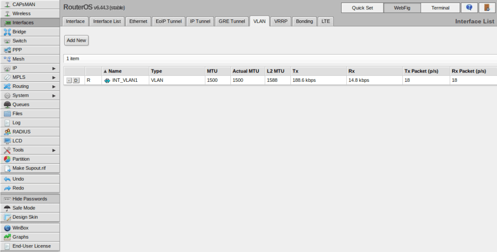
If you recall in part one, I created a VLAN interface in VLAN 1 to get management connectivity to the switch again. That interface is visible in the UI from the Interfaces/VLAN tab:
As a next step, I’ll create VLAN interfaces for the other five VLANs (11,76,98,2005 and 3156). Click the ‘Add New’ button to create a new one. I’ll start with VLAN 11 as an example.
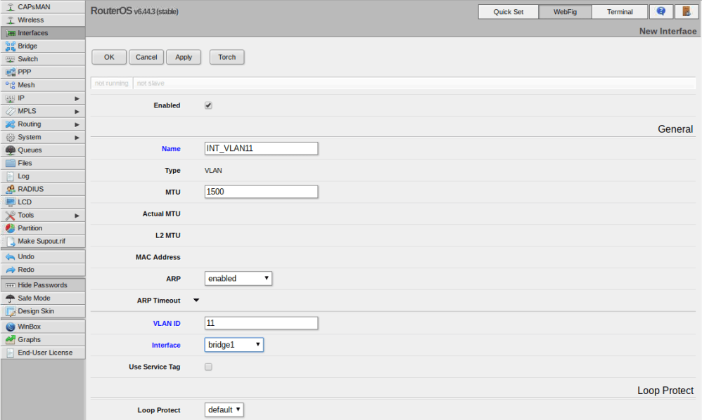
In my case there were only three options I needed to change – name, VLAN ID and Interface. I like to give my VLAN interfaces the names INT_VLANX for consistency. Be sure to assign the VLAN interface to the bridge that you created previously so that it is accessible from all ports on the switch. I repeated this for all of my VLANs.
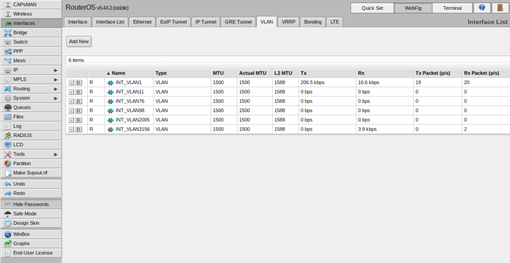
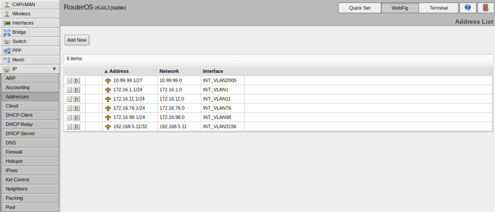
Now that these are all created and assigned to the bridge, we’ll need to give them IPs. You can do this from the IP/Addresses section. Again only INT_VLAN1 has an IP because we assigned this from the CLI in part one.
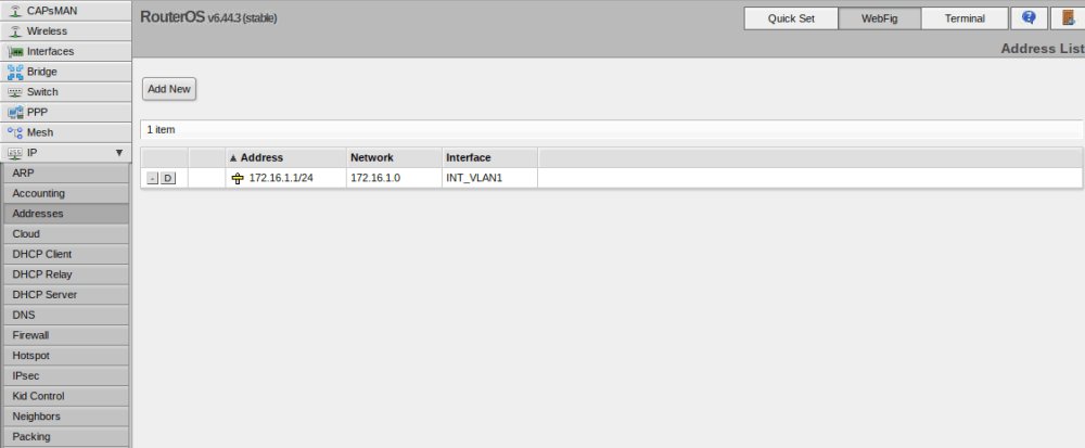
Click the Add New button. I’ll use VLAN11 as an example again.
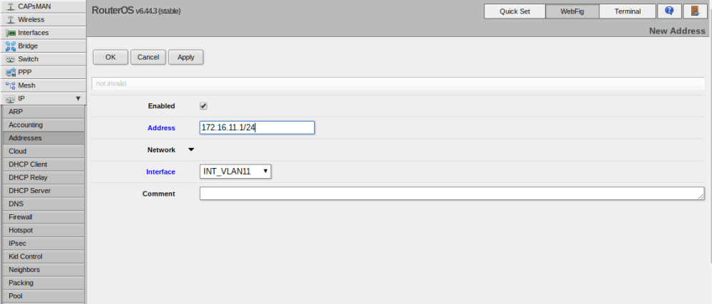
Simply select the VLAN interface you want to assign the IP to, and then enter the IP address in CIDR notation. In my case, VLAN 11 is 172.16.11.1 in a /24 subnet (255.255.255.0).
And that is basically it. Because the switch considers these VLAN interfaces ‘connected’ from a routing perspective, Inter-VLAN routing should immediately start working.
Checking the Routing Table
You can check the switch’s routing table by going to IP/Routes:
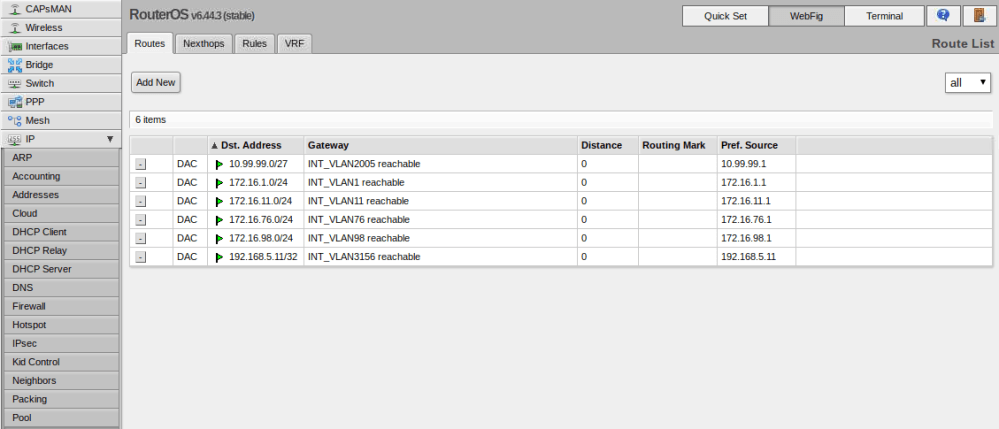
As you can see, all the networks associated with the VLAN interfaces are now in the table. If for whatever reason you want to prevent inter-VLAN routing between one or more of these interfaces, you can create firewall rules for this purpose. More on this in a future post.
You can also validate the routing table from the MikroTik CLI by running the /ip route print command:
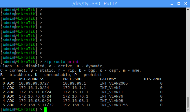
You can see the VLAN interfaces are always listed with ADC tags. Active, dynamically created – i.e. not added manually – and connected.
Conclusion
Once you understand the concept of the bridge interface on the CRS3xx series switches, the rest of the configuration should be more familiar. RouterOS provides a very impressive feature set. Being able to configure a full suite of routing features – including inter-VLAN routing – on a $269 10Gbps switch is fantastic. Stay tuned for some more configuration posts. Next up I’ll configure the switch for a 9K MTU.

I am a bit stupid with Mikrotik, did you create those VLANs on the switch itself or are they being trunked in from your router?
Hi Tom, all VLANs were created on the switch itself.
Hello, can you do performance tests using iperf3 when inter VLAN routing is in action? How much bandwidth CRS309 can route?
Hi Michal, I don’t have this switch any more unfortunately as I have downsized my home lab. I never paid much attention to the L3 throughput as I was most concerned with iSCSI and vMotion between ESX hosts.
hi, it’s very interresting to see that, i just buy one nov 2020 to replace and old hp workstation with VYOS and 3 SFP+ interfaces to bridge ESXI to Freenas and my workstation. Now i have CRS309, i think we can use them to route Gpon Bell Fiber to my network to bypass HH3000 Bell Router ? Do you think it has been a good project ? Challenge will be nice.
Where we can expect part 3 ? you said Stay tuned for some more configuration posts. Next up I’ll configure the switch for a 9K MTU. And im curisous about that.
Hi cscicus, I don’t have the CRS309 any more, unfortunately. I never got around to writing part three. I was hoping to buy the 16/17 port version but was unable to find one in stock where I live.
This is a great series. Thanks! I plan on simply using my MikrTik CRS309 for switching 10GbE within my ESXi/NSX-T lab. I used your first post to create my vlans on bridge1. I’ll deploy NSX-T and use that to create a vDS7,0 with my ESXi management traffic (ESXi/VSAN/VMOTION) and the NSX-T traffic (overlay and underlay). NSX-T will be doing all my required routing – so I don’t think there’s any need for me to configure inter vlan routing on the CRS309.
Do you see any issues with what I’m trying to do?