MikroTik CRS309 Configuration – Part 2

Configuring inter-VLAN routing on the MikroTik CRS309-1G-8S+IN and checking the routing table.

Welcome to part two of a series on configuring the MikroTik CRS309-1G-8S+IN for use in a VMware home lab. In part one, I discussed RouterOS and how to get VLAN trunking configured for all ports from the CLI. Today I’ll be configuring inter-VLAN routing. Keep in mind that I’m using the CRS309, but this should be applicable to the popular CRS317 and other CRS3xx switches running RouterOS as well.

As I mentioned in my unboxing and overview post, the CRS309 is a fully featured L3 switch. It uses the Marvell Prestera DX switching chip with a forwarding ASIC for line-rate L2 performance at very low power consumption levels. This is great for a home lab, because your non-routed vSAN, iSCSI and vMotion kernel traffic can take advantage of full 10Gbps line rate throughput. To use the L3 features, however, the CRS3xx switches rely on the integrated 32-bit ARM CPU cores in the Prestera DX. This means that things like inter-VLAN routing, firewalling and other L3/L4 features are done in software. MikroTik rates the switch for around 2.5Gbps for anything that will need to be processed by the CPU cores. None the less, this is still plenty of routing throughput for a home lab and I’m really happy that they include a huge number of these features even if they are somewhat performance limited.

VLAN Interface Creation

In the part one I relied on the CLI to get started. Now that we have a management IP configured, we can continue in the UI. To get inter-VLAN routing working on the CRS3xx series switches, there are two steps – first, we’ll need to create VLAN interfaces with the correct VLAN ID specified. Second, we need to assign an IP address to these interfaces.
If you recall in part one, I created a VLAN interface in VLAN 1 to get management connectivity to the switch again. That interface is visible in the UI from the Interfaces/VLAN tab:

crs309-intervlan-1

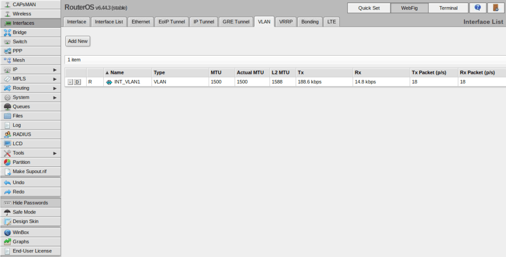
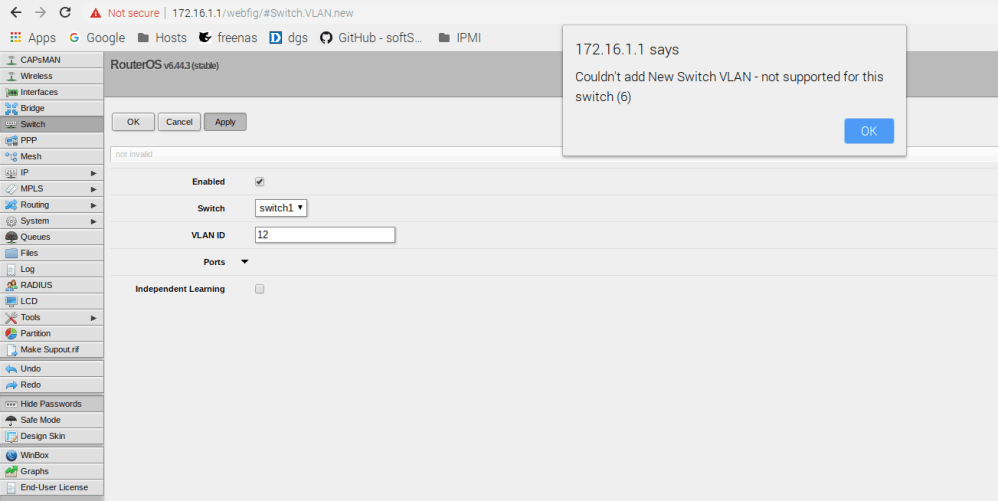
As a next step, I’ll create VLAN interfaces for the other five VLANs (11,76,98,2005 and 3156). Click the ‘Add New’ button to create a new one. I’ll start with VLAN 11 as an example.

crs309-intervlan-2

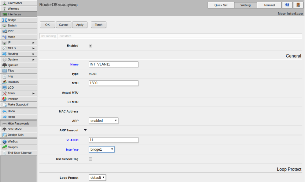
In my case there were only three options I needed to change – name, VLAN ID and Interface. I like to give my VLAN interfaces the names INT_VLANX for consistency. Be sure to assign the VLAN interface to the bridge that you created previously so that it is accessible from all ports on the switch. I repeated this for all of my VLANs.

Continue reading “MikroTik CRS309 Configuration – Part 2”

MikroTik CRS309 Configuration – Part 1

The first in a multi-part series on configuring the CRS309 for a VMware home lab. Part 1 covers 802.1q VLAN trunking.

This will be the first of several posts on configuring the new MikroTik CRS309-1G-8S+IN for use in a VMware home lab. Today’s first post will introduce MikroTik’s RouterOS and will focus on VLAN trunking. Please note that although this was written for the CRS309, this should be applicable to all CRS3xx series switches, including the popular CRS317.

RouterOS vs SwOS

MikroTik’s RouterOS firmware that comes pre-loaded on the switch is very feature rich with loads of L3 functionality. It has everything from BGP/OSPF, to firewalling, NAT, DHCP services – you name it. It’s a multi-purpose firmware that was originally created for MikroTik’s routers. Today, it works with many of their other products, including switches, and wireless devices. Because of this, it feels more like router firmware adapted for use with switches as opposed to something designed especially for them. Configuring RouterOS on the CRS309/CRS317 can be challenging and there is a learning curve to overcome – even for those with a lot of networking experience. Things get easier when you learn the terminology and understand what does and does not apply to a switch within RouterOS.

The CRS309 also includes ‘SwOS’ – a straight-forward L2 firmware that is designed especially for their switches. I found SwOS’s UI to be very intuitive and a lot more like what I’d expect to see on a switch. If you are not looking to use any of the advanced L3 features that RouterOS offers, I’d highly recommend using SwOS instead. There is no need to flash back and forth from RouterOS to SwOS and vice-versa. Both firmware packages coexist in the flash memory and you can easily switch back and forth as required.

Although SwOS could suffice for my needs in the home lab, I’m not one to shy away from a challenge and really want to be able to take advantage of some of the L3 features. If I could get them to work, I could potentially retire one or two virtual machines that I currently use for routing and firewalling.

802.1q VLAN Trunking

One of the first things I tried to do with the CRS309 was get a bunch of VLANs created and all the interfaces configured as 802.1q VLAN trunk ports. This is probably the most common VMware home lab requirement with 10Gbps networking. Each host will have a limited number of interfaces, so VLAN trunks are critical to separate out the various services.

When you get into the RouterOS WebFig interface, you’ll find several places where VLANs can be configured. My first attempt was under ‘Switch’ and ‘VLANs’ – sounds logical enough:

crs309-vlans1

But clearly this doesn’t work. There is also a section for VLANs under ‘Interfaces’, but this is for VLAN interface creation, which I’ll get into later. One of the first things to keep in mind with RouterOS is that a lot of the configuration relating to the switch – including VLAN configuration – is done in the ‘Bridge’ section – not the Switch section.

From the CRS3xx series manual:

“Since RouterOS v6.41 bridges provide VLAN aware Layer2 forwarding and VLAN tag modifications within the bridge. This set of features makes bridge operation more like a traditional Ethernet switch and allows to overcome Spanning Tree compatibility issues compared to configuration when tunnel-like VLAN interfaces are bridged..”

Another important thing to remember is that any VLAN related configuration you do in the bridge does not come into effect until an option called vlan-filtering is set to ‘yes’ for the bridge itself.

Continue reading “MikroTik CRS309 Configuration – Part 1”

MikroTik CRS309-1G-8S+IN

Initial impressions on a very energy efficient 10Gbps SFP+ switch and an excellent choice for a VMware home lab!

A little over a year ago I decided to get my lab 10Gbps capable. At the time, the Quanta LB6M seemed like the obvious choice with 24x SFP+ interfaces, several 1Gbps copper interfaces and a price tag of only $300 USD. It worked well in my lab, but as you can imagine, older 10Gbps technology is far from energy efficient. The switch idled at close to 130W, which wasn’t far off from all three of my compute hosts put together. It was also very loud with seven high-RPM 40mm fans. Even when at their lowest setting, these chassis and PSU fans were painfully loud. There is no doubt that this switch is more at home in a datacenter than a home lab. It wasn’t long before I started keeping an eye out for newer offerings based on more efficient and cost-effective technologies. That’s when I came across MikroTik’s latest 3xx series “Cloud Router Switches”.

The MikroTik CRS309-1G-8S+IN

MikroTik is a technology firm based out of Latvia and is well known for their unique networking products. They sell a range of switches, routers, wireless products and even their caseless RouterBOARD systems for those interested in doing custom routers.

I was originally looking to purchase the CRS309’s bigger brother – the CRS317. Feature-wise they are very similar, but the CRS317 doubles up on SFP+ and 1Gbps copper interfaces. With two SFP+ ports on each of my four ESXi hosts, the CRS309’s eight SFP+ ports seemed to be sufficient. The feature that sold me on the CRS309 as opposed to the CRS317, however, was its completely passive/fanless design. The CRS317’s fans only spin up if the unit gets hot, but I liked the simplicity of a completely fanless solution.

Feature-wise, the CRS309 is a pretty impressive switch. Its state of the art Marvell Prestera 98DX8208 switching chip (98DX8216 in the CRS317) is what makes this such an efficient unit. The 98DX8208 is highly integrated and is good for line rate forwarding on all the SFP+ ports. It also includes an integrated dual core 32-bit ARM based processor running 800MHz. You can find more information on the Marvell Prestera here. The flash storage is a pretty spartan 16MB, but this seems to be plenty for the RouterOS and SwOS firmware to coexist on the switch simultaneously. I’ll get more into the CRS309’s software in a future post.

From a L2 perspective, it’s a perfectly capable unit. It can do line-rate L1 and L2 forwarding at about 81,000Mbps aggregate, or 162,000 Mbps full-duplex. This is because the 98DX8208 has an ASIC switching component and all L2 forwarding is done in hardware. The L3 features of the switch, however, are all done in software and must be processed by the integrated ARM CPU cores. Based on MikroTik’s test results, about 2.5Gbps can be expected when traffic has to go through the CPU. Your mileage may vary though depending on the features you use. This may not sound great, but in a home lab environment, you don’t really need high throughput for inter-VLAN routing or other L3 features. I’m most interested in having 10Gbps line rate throughput for host-to-host VSAN traffic, iSCSI, vMotion etc. If you really do need faster routing, you could always spin up a VyOS VM and use your hypervisor’s horsepower for that purpose. Given the $269 USD price of the unit, I think it’s awesome that you get a full suite of L3 features even if throughput is somewhat limited.

You can find more information and the specifications of the CRS309 at Mikrotik’s site.

Continue reading “MikroTik CRS309-1G-8S+IN”

Noctua NH-U9DX i4 and NH-D9DX i4 3U Heatsink Review

There are many different approaches you can take when building a VMware home lab, but I always prefer to do custom-build tower systems. This allows me to select the components I want – the fans, heatsinks, PSU – to keep the noise to a minimum. Even though I keep the lab in the basement, I really don’t like to hear it running. I don’t need the density that a rack provides, and I’m quite happy to have my nearly silent towers humming along on a wire shelf instead. Not to mention that lower noise usually equates to lower power consumption and of course, it keeps my wife happy as well – the most critical metric of all.

I finally got around to upgrading my three ancient compute nodes recently. I have been using the included Dynatron R13 1U copper heatsinks that came with the motherboards I bought on eBay. They work, and keep the CPUs relatively cool, but as you can imagine, noise was not a key consideration in their design. They are as compact and as efficient as possible at only an inch tall. At idle, the Supermicro X9SRL-F keeps them at a low RPM, but put any load on the systems and you’re quickly at 7500RPM and the noise is pretty unbearable. No problem for a datacenter, but not for a home lab.

Today I’ll be taking a bit of a departure from my regular posts and will be doing an in-depth review of two high-end Noctua heatsinks. Noctua was kind enough to send me a review sample of not one, but two of their Xeon heatsinks – the NH-U9DX i4 and the NH-D9DX i4 3U.

Noctua

noctua_200x200px
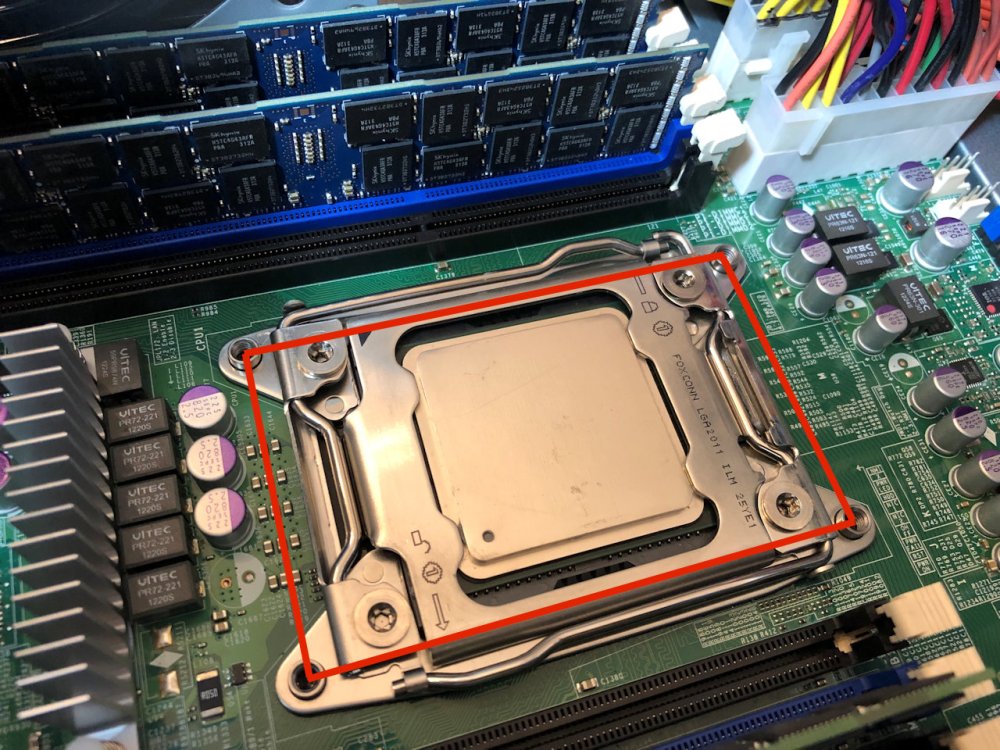
Noctua is an Austrian company well known for their low noise fans and high-end heatsinks. I’ve been using Noctua heatsinks for ages. In fact, I reviewed some of their original heatsinks and fans many years ago when I used to write hardware reviews. This included their original NH-U12P, the NH-C12P and the smaller NH-U9B. Back then, I praised them for their high-quality construction, near silent operation, excellent mounting hardware and most importantly – excellent cooling performance. That was over ten years ago, and it seems that Noctua is still very well respected for all the same reasons today.

Their gear has always been pricey compared to the competition, but when it comes to Noctua, you get what you pay for.

Square vs Narrow ILM LGA 2011

One of the challenges I had with my new/used Supermicro X9SRL-F boards is that they don’t use the common ‘square’ LGA2011 mounting pattern. Instead, they use what’s referred to as ‘Narrow ILM’ that allows the socket to be more rectangular in shape. This allows more real estate for memory slots and other components on the board. Because of this, I was severely limited in my heatsink choices. Most of what’s available out there for Narrow ILM are rack mount heatsinks similar to what I’m hoping to remove. The majority of the consumer-grade stuff for LGA2011 simply won’t fit.

noctuai4-24

Here you can see the Dynatron R13 narrow ILM heatsink mounted:

Continue reading “Noctua NH-U9DX i4 and NH-D9DX i4 3U Heatsink Review”

Home Lab Power Automation – Part 3

In part 2, I shared the PowerCLI scripting I used to power on my entire lab environment in the correct order. In this final installment, I’ll take you through the scripting used to power everything down. Although you may think the process is just the reverse of what I covered in part 2, you’ll see there were some other things to consider and different approaches required.

Step 1 – Shutting Down Compute Cluster VMs

To begin the process, I’d need to shut down all VMs in the compute-a cluster. None of the VMs there are essential for running the lab, so they can be safely stopped at any time. I was able to do this by connecting to vCenter with PowerCLI and then using a ‘foreach’ loop to gracefully shut down any VMs in the ‘Powered On’ state.

"Connecting to vCenter Server ..." |timestamp
Connect-VIServer -Server 172.16.1.15 -User administrator@vsphere.local -Password "VMware9("

"Shutting down all VMs in compute-a ..." |timestamp
$vmlista = Get-VM -Location compute-a | where{$_.PowerState -eq 'PoweredOn'}
foreach ($vm in $vmlista)
    {
    Shutdown-VMGuest -VM $vm -Confirm:$false | Format-List -Property VM, State
    }

The above scripting ensures the VMs start shutting down, but it doesn’t tell me that they completed the process. After this is run, it’s likely that one or more VMs may still be online. Before I can proceed, I need to check that they’re all are in a ‘Powered Off’ state.

"Waiting for all VMs in compute-a to shut down ..." |timestamp
do
{
    "The following VM(s) are still powered on:"|timestamp
    $pendingvmsa = (Get-VM -Location compute-a | where{$_.PowerState -eq 'PoweredOn'})
    $pendingvmsa | Format-List -Property Name, PowerState
    sleep 1
} until($pendingvmsa -eq $null)
"All VMs in compute-a are powered off ..."|timestamp

A ‘do until’ loop does the trick here. I simply populate the list of all powered on VMs into the $pendingvmsa variable and print that list. After a one second delay, the loop continues until the $pendingvmsa variable is null. When it’s null, I know all of the VMs are powered off and I can safely continue.

Continue reading “Home Lab Power Automation – Part 3”

Home Lab Power Automation – Part 2

In part 1, I shared some of the tools I’d use to execute the power on and shutdown tasks in my lab. Today, let’s have a look at my startup PowerCLI script.

A Test-Connection Cmdlet Replacement

As I started working on the scripts, I needed a way to determine if hosts and devices were accessible on the network. Unfortunately, the Test-Connection cmdlet was not available in the Linux PowerShell core release. It uses the Windows network stack to do its thing, so it may be a while before an equivalent gets ported to Linux. As an alternative, I created a simple python script that achieves the same overall result called pinghost.py. You can find more detail on how it works in a post I did a few months back here.

The script is very straightforward. You specify up to three space separated IP addresses or host names as command line arguments, and the script will send one ICMP echo request to each of the hosts. Depending on the response, it will output either ‘is responding’ or ‘is not responding’. Below is an example:

pi@raspberrypi:~/scripts $ python pinghost.py vc.lab.local 172.16.10.67 172.16.10.20
vc.lab.local is not responding
172.16.10.67 is responding
172.16.10.20 is not responding

Then using this script, I could create sleep loops in PowerShell to wait for one or more devices to become responsive before proceeding.

Adding Timestamps to Script Output

As I created the scripts, I wanted to record the date/time of each event and output displayed. In a sense, I wanted it to look like a log that could be written to a file and referred to later if needed. To do this, I found a simple PowerShell filter that could be piped to each command I ran:

#PowerShell filter to add date/timestamps
filter timestamp {"$(Get-Date -Format G): $_"}

Step 1 – Power On the Switch

Powering up the switch requires the use of the tplink_smartplug.py python script that I discussed in part 1. The general idea here is to instruct the smart plug to set its relay to a state of ‘1’. This brings the switch to life. I then get into a ‘do sleep’ loop in PowerCLI until the Raspberry Pi is able to ping the management interface of the switch. More specifically, it will wait until the pinghost.py script returns a string of “is responding”. If that string isn’t received, it’ll wait two seconds, and then try again.

"Powering up the 10G switch ..." |timestamp
/home/pi/scripts/tplink-smartplug-master/tplink_smartplug.py -t 192.168.1.199 -c on |timestamp

"Waiting for 10G switch to boot ..." |timestamp
do
{
$pingresult = python ~/scripts/pinghost.py 172.16.1.1 |timestamp
$pingresult
sleep 2
} until($pingresult -like '*is responding*')

When run, the output looks similar to the following:

Continue reading “Home Lab Power Automation – Part 2”

Home Lab Power Automation – Part 1

My home lab has grown substantially over the last few years and with it, so did power consumption, heat and noise. I selected power efficient parts where possible, but even with 500-600W power usage, 24/7 operation adds up. I can certainly notice the extra cost on my hydro bill, but it’s not just the financial impact – it’s also the environmental impact I’m concerned about.

The bottom line is that I have no reason to run the lab 24/7. I generally use it an hour or two each day – sometimes more, sometimes less. But there are also stretches where I won’t use it for several days like on weekends or when I’m busy with other things.

I found myself manually shutting down the lab when I knew I wouldn’t be using it and then manually powering everything back up. As you can imagine, this was quite a process. Everything had to be powered on or shut down in a very specific order to avoid problems. I’d also need to be standing in front of the equipment for part of this process as some equipment didn’t have remote power-on capability. Because of the work and time involved, I’d inevitably just leave it powered on for much longer stretches than I needed to.

It wasn’t until I added a 10Gbps Quanta LB6M switch to the lab that I realized I needed to do something. It’s not a quiet or energy efficient switch, consuming an average of 120W at idle.

Continue reading “Home Lab Power Automation – Part 1”

Home Lab

One of the most important tools I use day-to-day is my lab. Although I’m fortunate to have access to some shared lab resources at VMware, I still choose to maintain a dedicated home lab. I like to have the freedom to build it up, tear it down and configure it in any way I see fit.

I’ve had a few people ask me about my home lab recently, so I wanted to take a moment to share my setup. I’m not going to go too much into how I use the lab, or the software side of things but will stay focused on the hardware for now.

My Goals

I’ve had several iterations of home lab over the years, but my most recent overhaul was done about two years ago in 2016. At that time, I had several goals in mind:

  1. To keep cost low. I chose mainly EOL, second hand hardware that was relatively inexpensive. I often looked for the ‘sweet spot’ to get the best performance for the dollar.
  2. To use server/workstation grade hardware wherever possible. I’ve had some mixed experiences with consumer grade equipment and prefer having IPMI and being able to run large amounts of registered ECC memory.
  3. Low noise. I really didn’t like the noise and heat generated by rackmount gear and tried to stick with custom-build server systems wherever possible.
  4. Power efficiency. Building custom machines with simple cooling systems allowed me to keep power consumption down. I also didn’t see the point of running the lab 24/7 and chose to automate power on and power off activities.
  5. Sized right. Although more RAM and compute power is always desirable, I tried to keep things reasonably sized to keep costs and power consumption down. I wanted to be able to have some flexibility, but would try to keep VMs sized smaller and power down what I didn’t need.

The Lab

homelabv1

I’ll get more into each component, but here’s a summary:

  • 1x Management Node (2x Xeon E5-2670, 96GB RAM)
  • 3x Compute Nodes (Xeon X3440, 16GB RAM)
  • 1x FreeNAS Server (Dell T110, Xeon 3430, 8GB RAM)
  • 1x Raspberry Pi 3 Model B (Automation and remote access)
  • Quanta LB6M 24 port 10Gbps Switch (24x SFP+ ports)
  • D-link DGS-1210-16 Managed Switch (16x copper ports, 4x SFP)
  • Cyber Power PFCLCD1500 UPS system

All of the equipment sits comfortably in a wire shelf/rack in a corner of my unfinished basement. Here it can stay nice and cool and the noise it generates doesn’t bother anyone.

Continue reading “Home Lab”

Creating a Python Replacement for the Test-Connection cmdlet.

I’ve been working on a PowerShell script to automatically power up and shut down all devices in my home lab. Both in the interest of saving on hydro and to reduce it’s environmental impact. To do this, I’ve been using a low-power Raspberry Pi 3 B+, which will stay powered on to orchestrate these and other scripted activities.

One great PowerShell cmdlet that comes in handy is Test-Connection. Although it can be used for numerous network testing purposes, it’s most commonly used to send an ICMP echo request to a host to see if it responds or not. The cmdlet responds with a simple true or false response, which makes it very handy for scripting purposes. I was really hoping to use this cmdlet because it makes it easy to determine if a device is still online or not and if it’s okay to move on to the next phase of powering things on or shutting things down. For example, I don’t want to power on my management ESXi host until the freenas SAN is online.

The problem I ran into was that not all PowerShell cmdlets have been ported over to PowerShell Core for Linux. Test-Connection is unfortunately one of them due to the way it uses the Microsoft Windows network stack to function. Looking at the GitHub PR, it seems they are getting close to porting it over, but I decided to try my hand at creating a python script with similar basic functionality.

I should note that I’m not a programmer by any stretch of the imagination and it’s been many years since I’ve done any serious coding. This is actually the first bit of python code I’ve written, so I’m sure there are many more efficient ways to achieve what I’ve done here:

import os
import sys

# If no arguments parsed, display the greeting:
if len(sys.argv) == 1:
    print("vswitchzero.com ICMP response script. Specify up to 3 hosts to ping separated by spaces.")
    print("example: python ./pinghost.py 172.16.10.15 192.168.1.1 vc.lab.local")

# If one arg parsed, ping a single host
if len(sys.argv) == 2:
    host1 = sys.argv[1]
    response = os.system("ping -c 1 " + host1 + "> /dev/null")
    if response == 0:
        print host1, 'is responding'
    else:
        print host1, 'is not responding'

# If two args parsed, ping two hosts
if len(sys.argv) == 3:
    host1 = sys.argv[1]
    host2 = sys.argv[2]
    response1 = os.system("ping -c 1 " + host1 + "> /dev/null")
    if response1 == 0:
        print host1, 'is responding'
    else:
        print host1, 'is not responding'
    response2 = os.system("ping -c 1 " + host2 + "> /dev/null")
    if response2 == 0:
        print host2, 'is responding'
    else:
        print host2, 'is not responding'

# If three args parsed, ping three hosts
if len(sys.argv) == 4:
    host1 = sys.argv[1]
    host2 = sys.argv[2]
    host3 = sys.argv[3]
    response1 = os.system("ping -c 1 " + host1 + "> /dev/null")
    if response1 == 0:
        print host1, 'is responding'
    else:
        print host1, 'is not responding'
    response2 = os.system("ping -c 1 " + host2 + "> /dev/null")
    if response2 == 0:
        print host2, 'is responding'
    else:
        print host2, 'is not responding'
 response3 = os.system("ping -c 1 " + host3 + "> /dev/null")
    if response3 == 0:
        print host3, 'is responding'
    else:
        print host3, 'is not responding'

# If more than three args parsed, display an error
if len(sys.argv) > 4:
    print('vswitchzero.com ICMP response script. Specify up to 3 hosts to ping separated by spaces.')
    print('example: python ./pinghost.py 172.16.10.15 192.168.1.1 vc.lab.local')
    print(' ')
    print('ERROR: Too many arguments specified. Use 1-3 IPs or hostnames only. Each should be separated by a space')

Continue reading “Creating a Python Replacement for the Test-Connection cmdlet.”