SR-IOV or “Single Root I/O Virtualization” is a very interesting feature that can provide virtual machines shared access to physical network cards installed in the hypervisor. This may sound a lot like what a virtual NIC and a vSwitch does, but the feature works very similarly to PCI passthrough, granting a VM direct access to the NIC hardware. In order to understand SR-IOV, it helps to understand how PCI passthrough works. Here is a quote from a post I did a few years ago:
“PCI Passthrough – or VMDirectPath I/O as VMware calls it – is not at all a new feature. It was originally introduced back in vSphere 4.0 after Intel and AMD introduced the necessary IOMMU processor extensions to make this possible. For passthrough to work, you’ll need an Intel processor supporting VT-d or an AMD processor supporting AMD-Vi as well as a motherboard that can support this feature.
In a nutshell, PCI passthrough allows you to give a virtual machine direct access to a PCI device on the host. And when I say direct, I mean direct – the guest OS communicates with the PCI device via IOMMU and the hypervisor completely ignores the card.”
SR-IOV takes PCI passthrough to the next level. Rather than granting exclusive use of the device to a single virtual machine, the device is shared or ‘partitioned’. It can be shared between multiple virtual machines, or even shared between virtual machines and the hypervisor itself. For example, a single 10Gbps NIC could be ‘passed through’ to a couple of virtual machines for direct access, and at the same time it could be attached to a vSwitch being used by other VMs with virtual NICs and vmkernel ports too. Think shared PCI passthrough.
Configuring inter-VLAN routing on the MikroTik CRS309-1G-8S+IN and checking the routing table.
Welcome to part two of a series on configuring the MikroTik CRS309-1G-8S+IN for use in a VMware home lab. In part one, I discussed RouterOS and how to get VLAN trunking configured for all ports from the CLI. Today I’ll be configuring inter-VLAN routing. Keep in mind that I’m using the CRS309, but this should be applicable to the popular CRS317 and other CRS3xx switches running RouterOS as well.
As I mentioned in my unboxing and overview post, the CRS309 is a fully featured L3 switch. It uses the Marvell Prestera DX switching chip with a forwarding ASIC for line-rate L2 performance at very low power consumption levels. This is great for a home lab, because your non-routed vSAN, iSCSI and vMotion kernel traffic can take advantage of full 10Gbps line rate throughput. To use the L3 features, however, the CRS3xx switches rely on the integrated 32-bit ARM CPU cores in the Prestera DX. This means that things like inter-VLAN routing, firewalling and other L3/L4 features are done in software. MikroTik rates the switch for around 2.5Gbps for anything that will need to be processed by the CPU cores. None the less, this is still plenty of routing throughput for a home lab and I’m really happy that they include a huge number of these features even if they are somewhat performance limited.
VLAN Interface Creation
In the part one I relied on the CLI to get started. Now that we have a management IP configured, we can continue in the UI. To get inter-VLAN routing working on the CRS3xx series switches, there are two steps – first, we’ll need to create VLAN interfaces with the correct VLAN ID specified. Second, we need to assign an IP address to these interfaces.
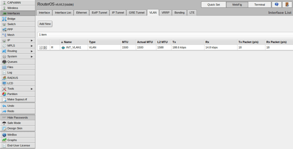
If you recall in part one, I created a VLAN interface in VLAN 1 to get management connectivity to the switch again. That interface is visible in the UI from the Interfaces/VLAN tab:
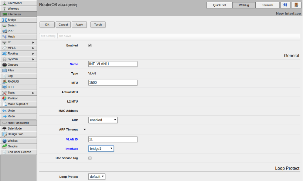
As a next step, I’ll create VLAN interfaces for the other five VLANs (11,76,98,2005 and 3156). Click the ‘Add New’ button to create a new one. I’ll start with VLAN 11 as an example.
In my case there were only three options I needed to change – name, VLAN ID and Interface. I like to give my VLAN interfaces the names INT_VLANX for consistency. Be sure to assign the VLAN interface to the bridge that you created previously so that it is accessible from all ports on the switch. I repeated this for all of my VLANs.
The first in a multi-part series on configuring the CRS309 for a VMware home lab. Part 1 covers 802.1q VLAN trunking.
This will be the first of several posts on configuring the new MikroTik CRS309-1G-8S+IN for use in a VMware home lab. Today’s first post will introduce MikroTik’s RouterOS and will focus on VLAN trunking. Please note that although this was written for the CRS309, this should be applicable to all CRS3xx series switches, including the popular CRS317.
RouterOS vs SwOS
MikroTik’s RouterOS firmware that comes pre-loaded on the switch is very feature rich with loads of L3 functionality. It has everything from BGP/OSPF, to firewalling, NAT, DHCP services – you name it. It’s a multi-purpose firmware that was originally created for MikroTik’s routers. Today, it works with many of their other products, including switches, and wireless devices. Because of this, it feels more like router firmware adapted for use with switches as opposed to something designed especially for them. Configuring RouterOS on the CRS309/CRS317 can be challenging and there is a learning curve to overcome – even for those with a lot of networking experience. Things get easier when you learn the terminology and understand what does and does not apply to a switch within RouterOS.
The CRS309 also includes ‘SwOS’ – a straight-forward L2 firmware that is designed especially for their switches. I found SwOS’s UI to be very intuitive and a lot more like what I’d expect to see on a switch. If you are not looking to use any of the advanced L3 features that RouterOS offers, I’d highly recommend using SwOS instead. There is no need to flash back and forth from RouterOS to SwOS and vice-versa. Both firmware packages coexist in the flash memory and you can easily switch back and forth as required.
Although SwOS could suffice for my needs in the home lab, I’m not one to shy away from a challenge and really want to be able to take advantage of some of the L3 features. If I could get them to work, I could potentially retire one or two virtual machines that I currently use for routing and firewalling.
802.1q VLAN Trunking
One of the first things I tried to do with the CRS309 was get a bunch of VLANs created and all the interfaces configured as 802.1q VLAN trunk ports. This is probably the most common VMware home lab requirement with 10Gbps networking. Each host will have a limited number of interfaces, so VLAN trunks are critical to separate out the various services.
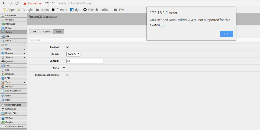
When you get into the RouterOS WebFig interface, you’ll find several places where VLANs can be configured. My first attempt was under ‘Switch’ and ‘VLANs’ – sounds logical enough:
But clearly this doesn’t work. There is also a section for VLANs under ‘Interfaces’, but this is for VLAN interface creation, which I’ll get into later. One of the first things to keep in mind with RouterOS is that a lot of the configuration relating to the switch – including VLAN configuration – is done in the ‘Bridge’ section – not the Switch section.
“Since RouterOS v6.41 bridges provide VLAN aware Layer2 forwarding and VLAN tag modifications within the bridge. This set of features makes bridge operation more like a traditional Ethernet switch and allows to overcome Spanning Tree compatibility issues compared to configuration when tunnel-like VLAN interfaces are bridged..”
Another important thing to remember is that any VLAN related configuration you do in the bridge does not come into effect until an option called vlan-filtering is set to ‘yes’ for the bridge itself.
Manually patching standalone ESXi hosts without access to vCenter or Update Manager using offline bundles and the CLI.
There are many different reasons you may want to patch your ESXi host. VMware regularly releases bug fixes and security patches, or perhaps you need a newer build for compatibility with another application or third-party tool.
Update 3/15/2021: See my video tutorial on how to update your ESXi 7.x host from the CLI:
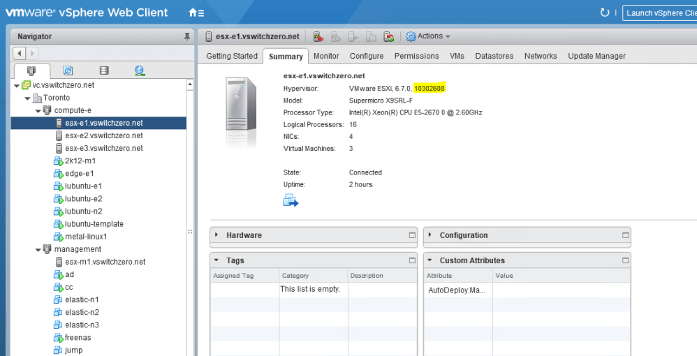
In my situation, the ESXi 6.7 U1 ESXi hosts (build 10302608) are not compatible with NSX-T 2.4.0, so I need to get them patched to at least 6.7 EP06 (build 11675023).
Before you get started, you’ll want to figure out which patch release you want to update to. There is quite often some confusion surrounding the naming of VMware patch releases. In some cases, a build number is referenced, for example, 10302608. In other cases, a friendly name is referenced – something like 6.7 EP06 or 6.5 P03. The EP in the name denotes an ‘Express Patch’ with a limited number of fixes released outside of the regular patch cadence, where as a ‘P’ release is a standard patch. In addition to this, major update releases are referred to as ‘U’, for example, 6.7 U1. And to make things more confusing, a special ‘Release Name’ is quite often referenced in security bulletins and other documents. Release names generally contain the release date in them. For example, ESXi670-201903001 for ESXi 6.7 EP07.
The best place to start is VMware KB 1014508, which provides links to numerous KB articles that can be used for cross referencing build numbers with friendly versions names. The KB we’re interested in for ESXi is KB 2143832.
Welcome to the second installment of a new series of NSX-T troubleshooting scenarios. Thanks to everyone who took the time to comment on the first half of the scenario. Today I’ll be performing some troubleshooting and will show how I came to the solution.
Please see the first half for more detail on the problem symptoms and some scoping.
Getting Started
As we saw in the first half, our fictional customer was having northbound communication problems because the physical core router was not getting any of the NSX advertised routes:
vyos@router-core:~$ sh ip route
Codes: K - kernel route, C - connected, S - static, R - RIP, O - OSPF,
B - BGP, > - selected route, * - FIB route

S>* 0.0.0.0/0 [1/0] via 172.16.1.12, eth0.1
C>* 10.99.99.0/27 is directly connected, eth0.2005
C>* 127.0.0.0/8 is directly connected, lo
C>* 172.16.1.0/24 is directly connected, eth0.1
C>* 172.16.11.0/24 is directly connected, eth0.11
C>* 172.16.76.0/24 is directly connected, eth0.76
C>* 172.16.98.0/24 is directly connected, eth0.98
Based on what we observed in the first half, we can make a few assertions:
The T1 routers are advertising their routes just fine to the T0 (a total of 8 routes).
The T0 router is peering with the core router successfully because we received BGP routes from the core router.
The T0 router is configured for route redistribution of NSX connected and Static routes.
Let’s just run through a couple of quick tests to confirm point one above and make sure that the T0 can communicate with the core router. From VRF 2 (the T0 SR), we’ll check the interface IP first:
Welcome to the second NSX-T troubleshooting scenario! What I hope to do in these posts is share some of the common issues I run across from day to day. Each scenario will be a two-part post. The first will be an outline of the symptoms and problem statement along with bits of information from the environment. The second will be the solution, including the troubleshooting and investigation I did to get there.
The Scenario
As always, we’ll start with a fictional customer problem statement:
“I’ve just deployed a new NSX-T 2.3.1 environment with two tenants. The T1 routers (one per tenant) appear to be working fine. I have VM to VM connectivity on logical switches, but I can’t get to any northbound networks. The non-NSX core router isn’t getting any of the NSX routes!”
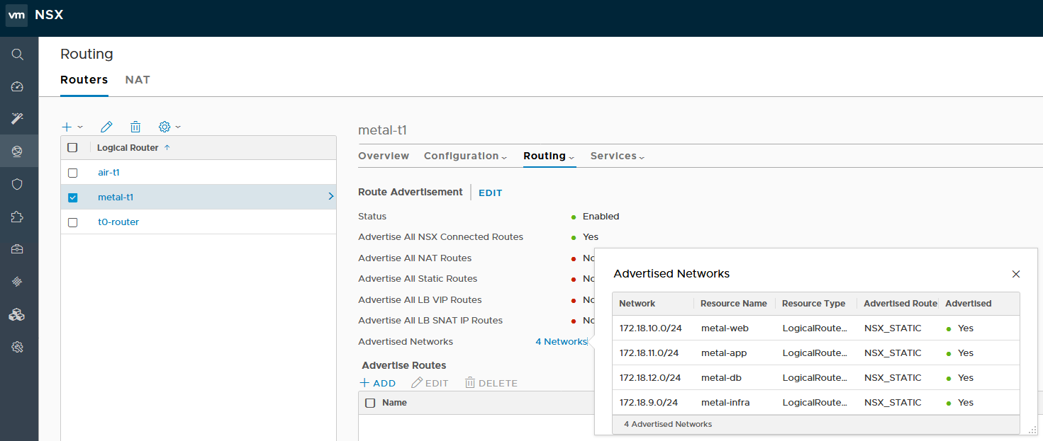
Taking a quick look at the environment, we can see that each tenant T1 router has several logical switches attached. Each is advertising four subnets as can be seen below:
You can also see that the ‘Advertise All NSX Connected Routes’ option is enabled, which should cause these routes to be advertised to the T0.
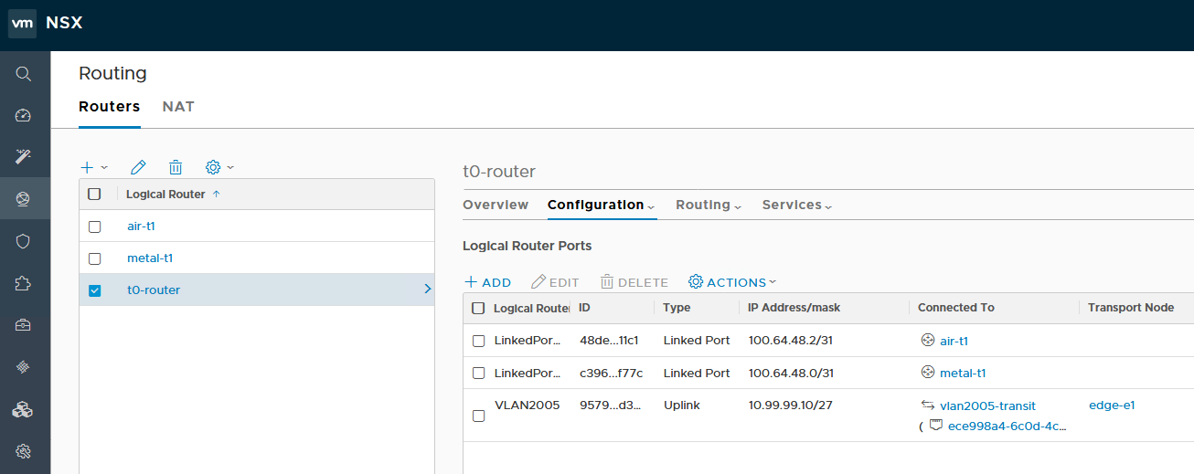
On the T0, we can see that there are ‘Linked Ports’ to both T1 routers, as well as a VLAN-backed logical switch for northbound communication via edge-e1. Let’s start by ensuring that these routes are actually making it to the T0 SR.
From the edge CLI, I start by listing all logical router instances to determine the VRF for the T0 SR:
New CPU requirements for NSX-T may leave older lab hardware out in the cold.
If you are running old hardware in your lab, you may have come across an unexpected failure while deploying your first NSX-T edge VM.
The exact error message will be something similar to:
“[Fabric] Edge <uuid> is not ready for configuration error occurred, error detail is NSX Edge configuration has failed. The host does not support required cpu features: [‘aes’].”
The edge will be successfully deployed, but will remain ‘unconfigured’ and will not allow you to add it as a transport node.
The ‘aes’ feature being referred to is Intel’s AES-NI acceleration for cryptography. You can find out more about AES-NI here. In NSX-V, AES-NI was optionally supported for offloading cryptography for VPN related features. It seems that this has now become a hard requirement for NSX-T.
Unfortunately, like vSphere 6.7, NSX-T has minimum CPU requirements that can’t be worked around. If you have a browse through the NSX-T system requirements, you’ll find a note about CPU compatibility in the “NSX Edge VM and Bare-Metal NSX Edge CPU Requirements” section. Listed there is reference to:
Xeon 56xx (Westmere-EP)
Xeon E7-xxxx (Westmere-EX and later CPU generation)
Xeon E5-xxxx (Sandy Bridge and later CPU generation)
This means that anything released prior to 2011 is unlikely to work, with the exception of a few Westermere EP based Xeons, which seem to have spotty success. On the AMD front, it appears that even CPUs with AES instructions will fail similarly due to a CPU compatibility check that is done during edge deployment.
Update: Commenter Ben Kenobi figured out a workaround to get edges to deploy on modern AMD platforms! You can find his workaround discussed below in the comments as well as on his blog here.
My management host uses Xeon E5-2670s, which work fine, but my compute cluster uses very old Xeon X3440s that came out before AES-NI was introduced. Now that I can’t run vSphere 6.7 or an NSX-T edge on these hosts, I think it may finally be time to upgrade.
Unfortunately, it doesn’t appear that there is a workaround for this problem. If anyone does come across a way to avoid this, please let me know!
I’ve been using FreeNAS for several years now for both block and NFS storage in my home lab with great success. For more information on my most recent FreeNAS build, you can check out the series here.
Although I’ve been quite pleased with this setup, I had to repurpose the SSDs in the box and had yet another USB boot device failure. This meant I had to reinstall FreeNAS and left me with just a single ZFS pool with a pair of 2TB mechanical drives. It just didn’t feel right to have a full system up and running for just a pair of 2TB drives when I could run them just fine in my management ESXi host. Not to mention the fact that I’ve got 224GB of RAM available there to provide for a much larger L1 ARC cache.
In part 2 of my FreeNAS build series, I looked at using VT-d to passthrough a proper LSI SAS HBA to a VM. This is really the best possible virtual FreeNAS configuration as it bypasses all of the hypervisor’s storage stack and grants direct access to the HBA and drives. I considered using this setup, but I didn’t think it was worth the extra power consumption and cooling needed for the toasty PERC H200 card I’ve been using. Since I wanted to preserve all data on the drives, RDMs seemed to be the next logical solution. This isn’t as ‘pure’ as the VT-d solution, but it still gives the VM full block access to the drives in the system. At any rate, it was worth a try!
Disclaimer: If you are using ZFS and FreeNAS for production purposes or for any critical data that you care about, using a proper physical setup is important. I wouldn’t recommend virtualizing FreeNAS or any other ZFS based storage system for anything but testing or lab purposes.
What I hoped to do was the following:
Take the 2x2TB Western Digital hard drives out of the Dell T110.
Re-install the 2x2TB drives in my Intel S2600 management host on the integrated SATA controller.
Create a new FreeNAS virtual machine.
Add the two drives to the VM as virtual mode RDMs.
Import the existing ZFS volume that is striped across these two drives in FreeNAS.
Re-create the iSCSI target and NFS shares and have access to all existing data in the pool! (assuming all goes well).
Creating a new FreeNAS VM
Once I got the two drives installed in my Intel S2600 management host, I created a new VM and got the FreeNAS OS installed. Below is the virtual hardware configuration I used:
Guest OS type: Other, FreeBSD 64-bit CPUs: 2x vCPUs Memory: 16GB (a minimum of 8GB is required) Hard Disk: 16GB (for the FreeNAS OS boot device, a minimum of 8GB is required) New SCSI controller: LSI Logic SAS Network adapter type: VMXNET3 CD/DVD Drive: Mount the FreeNAS 11.2 ISO from a datastore
You’ll notice that some of the options I selected are not defaults for FreeBSD based VMs. This includes the LSI SAS adapter, and the VMware VMXNET3 NIC. LSI Parallel is the default for FreeBSD VMs, but the SAS adapter works well with all recent BSD builds. The same holds true for the VMXNET3 adapter, which has many benefits over the emulated E1000 adapter type.
Deploying an NSX-T control cluster manually for maximum control and flexibility.
One of the great things about NSX-T is its complete independence from vCenter Server. You can still link to vCenter Server if you’d like to automate certain tasks, but unlike NSX-V, you can accomplish many deployment tasks manually. One of the firsts things you’ll be doing in a new NSX-T setup is to deploy your control cluster.
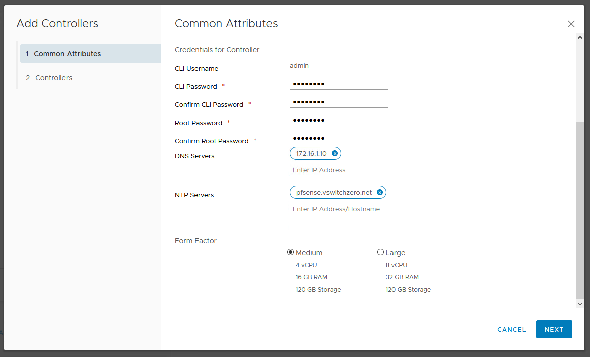
Although automated deployment through vCenter and the UI is convenient, there are some additional benefits to manual controller deployment. Firstly, you can select a non-production ‘small’ sized form factor that isn’t selectable in the UI saving you a couple of vCPUs and about 8GB of RAM per appliance. Secondly, deploying manually also allows you to thin-provision your controller VMDKs off the bat. In a home lab, these are some desirable benefits. And of course, there is always the satisfaction you get from running through the process manually and better understanding what happens behind the scenes.
As seen above, the automated controller deployment wizard does not allow the selection of a ‘Small’ form factor.
Deploying Controllers
To begin, you’ll need to download the NSX-T controller OVA. You’ll find it listed along with the other NSX-T deliverables on the download page.
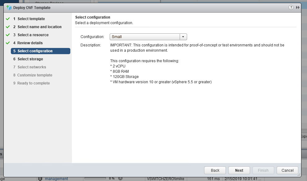
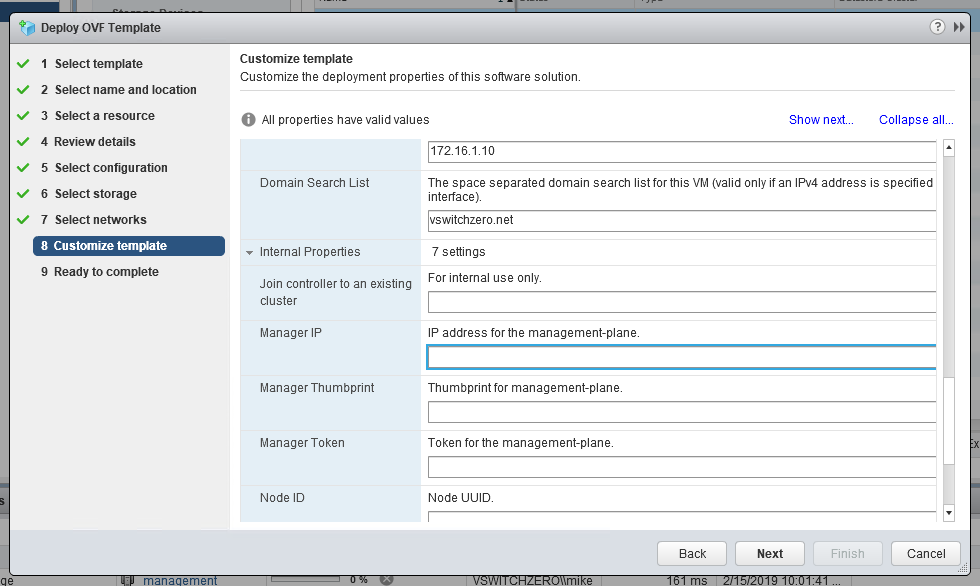
There are a few different ways that you can deploy the OVA including with ovftool. I’m just going to use the vSphere Client for this example. As you can see below, we can now select an unsupported ‘Small’ form-factor deployment:
In addition to this, you’ll get the usual template customization options along with a few new ones you may not have seen listed under ‘Internal Properties’:
As you probably have guessed these internal properties can be used to save some of the work needed to get it connected to the management plane and to the control cluster. I’m going to skip this entire section and run through the process manually from the CLI post-deployment.
Using NSX REST API calls to modify ESG/DLR configuration that isn’t exposed in the UI.
If you are reading this post, you’ve probably already come to the realization that the ‘Tenant’ field for ESGs can’t be changed in the UI. Once the appliance is deployed, this string value appears set in stone.
Adding the Tenant and Description are easy during deployment, but can’t be changed in the UI after deployment.
Although it can’t be modified in the UI without creating a new appliance from scratch, it’s pretty easy to modify this field via REST API calls. After having come across a question on the VMware communities forum regarding this, I thought I’d write a quick post on the process.
Step 1: Retrieve the ESG/DLR Configuration
First, you’ll need to do a GET call to retrieve the current ESG/DLR configuration in XML format. I won’t cover the basics of REST API calls in this post as the topic is well covered elsewhere. If you’ve never done REST API calls before, I’d recommend doing some reading on the subject before proceeding.
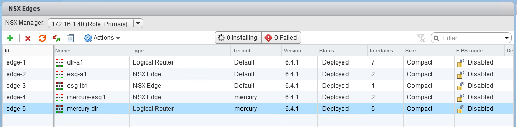
I’ll be using the popular Postman utility for this. First, we’ll need to find the moref identifier of the ESG/DLR in question.
We’re interested in mercury-esg1, which is edge-4 in my lab environment.
You can easily find this from the ‘Edges’ view in the UI. In my case, I want to modify the edge called mercury-esg1, which is edge-4. Notice that someone put the string ‘test’ in as the tenant, which we want to change to ‘mercury’.
From Postman, we’ll run the following API call to retrieve edge-4’s configuration:
GET https://<nsxmgrip>/api/4.0/edges/edge-4
I got a 200 OK response, with all the config in XML format returned.
All of the ESG’s configuration was returned in XML format. This is everything needed to recreate or modify the appliance.
Step 2: Make the Necessary Changes
Next, I’ll copy and paste all the returned XML data into a text editor. The XML section for the tenant string is right near the top:
I will simply change <tenant>test</tenant> to <tenant>mercury</tenant>.
Step 3: Apply the Modified Configuration
The final step is to take your modified XML configuration data and apply it back to the ESG/DLR in question. This is as simple as changing your REST API call from GET to PUT and pasting the modified configuration into the ‘Body’ of the call.
Be sure to double check your configuration before sending the PUT call!
If your call was successful, you should get a 204 No Content response.
And there you have it – the tenant field has been updated. Unfortunately, I haven’t had any success updating the description field via API. The <description> tag appears to be ignored in this PUT call for some reason. If anyone has any success with this, please let me know.
PowerNSX Alternative
If you prefer using PowerNSX to API calls, the Set-NsxEdge cmdlet can also work. The cmdlet uses the same API calls behind the scene, but can be quicker to execute:
PS C:\Users\mike.VSWITCHZERO> $edge = get-nsxedge mercury-esg1PS C:\Users\mike.VSWITCHZERO> $edge.tenant = "hello"PS C:\Users\mike.VSWITCHZERO> set-nsxedge $edge
Edge Services Gateway update will modify existing Edge configuration.
Proceed with Update of Edge Services Gateway mercury-esg1?
[Y] Yes [N] No [?] Help (default is "N"): y
id : edge-4
version : 37
status : deployed
datacenterMoid : datacenter-2
datacenterName : Toronto
tenant : hello
name : mercury-esg1
fqdn : mercury-esg1.mercury.local
enableAesni : true
enableFips : false
vseLogLevel : info
vnics : vnics
appliances : appliances
cliSettings : cliSettings
features : features
autoConfiguration : autoConfiguration
type : gatewayServices
isUniversal : false
hypervisorAssist : false
tunnels :
edgeSummary : edgeSummary