ECMP or ‘equal cost multi-pathing’ is a great routing feature that was introduced in NSX 6.1 several years ago. By utilizing multiple egress paths, ECMP allows for better use of network bandwidth for northbound destinations in an NSX environment. As many as eight separate ESG appliances can be used with ECMP – ideally on dedicated ESX hosts in an ‘edge cluster’.
Lab Setup
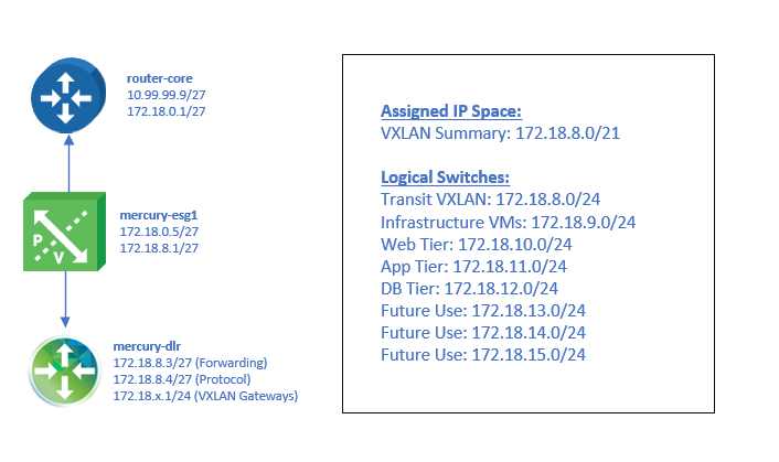
In my lab, I’ve configured a very simple topology with two ESXi hosts, each with an ESG appliance used for north/south traffic. The two ESGs are configured for ECMP operation:
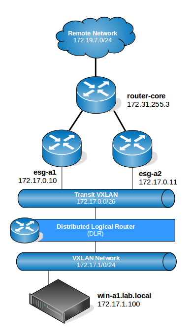
The diagram above is very high-level and doesn’t depict the underlying physical infrastructure or ESXi hosts, but should be enough for our purposes. BGP is used exclusively as the dynamic routing protocol in this environment.
Looking at the diagram, we can see that any VMs on the 172.17.1.0/24 network should have a DLR LIF as their default gateway. Because ECMP is being used, the DLR instance should in theory have an equal cost route to all northbound destinations via 172.17.0.10 and 172.17.0.11.
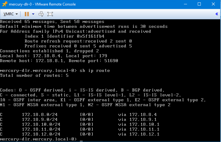
Let’s have a look at the DLR routing table:
dlr-a1.lab.local-0> sh ip route

Codes: O - OSPF derived, i - IS-IS derived, B - BGP derived,
C - connected, S - static, L1 - IS-IS level-1, L2 - IS-IS level-2,
IA - OSPF inter area, E1 - OSPF external type 1, E2 - OSPF external type 2,
N1 - OSPF NSSA external type 1, N2 - OSPF NSSA external type 2

Total number of routes: 17

B 10.40.0.0/25 [200/0] via 172.17.0.10
B 10.40.0.0/25 [200/0] via 172.17.0.11
C 169.254.1.0/30 [0/0] via 169.254.1.1
B 172.16.10.0/24 [200/0] via 172.17.0.10
B 172.16.10.0/24 [200/0] via 172.17.0.11
B 172.16.11.0/24 [200/0] via 172.17.0.10
B 172.16.11.0/24 [200/0] via 172.17.0.11
B 172.16.12.0/24 [200/0] via 172.17.0.10
B 172.16.12.0/24 [200/0] via 172.17.0.11
B 172.16.13.0/24 [200/0] via 172.17.0.10
B 172.16.13.0/24 [200/0] via 172.17.0.11
B 172.16.14.0/24 [200/0] via 172.17.0.10
B 172.16.14.0/24 [200/0] via 172.17.0.11
B 172.16.76.0/24 [200/0] via 172.17.0.10
B 172.16.76.0/24 [200/0] via 172.17.0.11
C 172.17.0.0/26 [0/0] via 172.17.0.2
C 172.17.1.0/24 [0/0] via 172.17.1.1
C 172.17.2.0/24 [0/0] via 172.17.2.1
C 172.17.3.0/24 [0/0] via 172.17.3.1
C 172.17.4.0/24 [0/0] via 172.17.4.1
C 172.17.5.0/24 [0/0] via 172.17.5.1
B 172.19.7.0/24 [200/0] via 172.17.0.10
B 172.19.7.0/24 [200/0] via 172.17.0.11
B 172.19.8.0/24 [200/0] via 172.17.0.10
B 172.19.8.0/24 [200/0] via 172.17.0.11
B 172.31.255.0/26 [200/0] via 172.17.0.10
B 172.31.255.0/26 [200/0] via 172.17.0.11
As seen above, all of the BGP learned routes from northbound locations – 172.19.7.0/24 included – have both ESGs listed with a cost of 200. In theory, the DLR could use either of these two paths for northbound routing. But which path will actually be used?
Path Determination and Hashing
In order for ECMP to load balance across multiple L3 paths effectively, some type of a load balancing algorithm is required. Many physical L3 switches and routers use configurable load balancing algorithms including more complex ones based on a 5-tuple hash taking even source/destination TCP ports into consideration. The more potential criteria for for analysis by the algorithm, the more likely traffic will be well balanced.
NSX’s implementation of ECMP does not include a configurable algorithm, but rather keeps things simple by using a hash based on the source and destination IP address. This is very similar to the hashing used by static etherchannel bonds – IP hash as it’s called in vSphere – and is generally not very resource intensive to calculate. With a large number of source/destination IP address combinations, a good balance of traffic across all paths should be attainable.
A few years ago, I wrote an article for the VMware Support Insider blog on manually calculating the hash value and determining the uplink when using IP hash load balancing. The general concept used by NSX for ECMP calculations is pretty much the same. Rather than calculating an index value associated with an uplink in a NIC team, we calculate an index value associated with an entry in the routing table.
Obviously, the most simple method of determining the path used would be a traceroute from the source machine. Let’s do this on the win-a1.lab.local virtual machine:
C:\Users\Administrator>tracert -d 172.19.7.100

Tracing route to 172.19.7.100 over a maximum of 30 hops

 1 <1 ms <1 ms <1 ms 172.17.1.1
 2 4 ms <1 ms <1 ms 172.17.0.10
 3 1 ms 1 ms 1 ms 172.31.255.3
 4 2 ms 1 ms <1 ms 10.40.0.7
 5 4 ms 1 ms 1 ms 172.19.7.100

Trace complete.
The first hop, 172.17.1.1 is the DLR LIF address – the default gateway of the VM. The second hop, we can see is 172.17.0.10, which is esg-a1. Clearly the hashing algorithm picked the first of two possible paths in this case. If I try a different northbound address, in this case 172.19.7.1, which is a northbound router interface, we see a different result:
C:\Users\Administrator>tracert -d 172.19.7.1

Tracing route to 172.19.7.1 over a maximum of 30 hops

 1 <1 ms <1 ms <1 ms 172.17.1.1
 2 <1 ms <1 ms <1 ms 172.17.0.11
 3 1 ms 1 ms 1 ms 172.31.255.3
 4 2 ms 1 ms 1 ms 172.19.7.1

Trace complete.
This destination uses esg-a2. If you repeat the traceroute, you’ll notice that as long as the source and destination IP address remains the same, the L3 path up to the ESGs also remains the same.
Traceroute is well and good, but what if you don’t have access to SSH/RDP into the guest? Or if you wanted to test several hypothetical IP combinations?
Using net-vdr to Determine Path
Thankfully, NSX includes a special net-vdr option to calculate the expected path. Let’s run it through its paces.
Keep in mind that because the ESXi hosts are actually doing the datapath routing, it’s there that we’ll need to do this – not on the DLR control VM appliance. Since my source VM win-a1 is on host esx-a1, I’ll SSH there. It should also be noted that it really doesn’t matter which ESXi host you use to check the path. Because the DLR instance is the same across all configured ESXi hosts, the path selection is also the same.
First, we determine the name of the DLR instance using the net-vdr -I -l command:
[root@esx-a1:~] net-vdr -I -l

VDR Instance Information :
---------------------------

Vdr Name: default+edge-1
Vdr Id: 0x00001388
Number of Lifs: 6
Number of Routes: 16
State: Enabled
Controller IP: 172.16.10.43
Control Plane IP: 172.16.10.21
Control Plane Active: Yes
Num unique nexthops: 2
Generation Number: 0
Edge Active: No
In my case, I’ve got only one instance called default+edge-1. The ‘Vdr Name’ will include the tenant name, followed by a ‘+’ and then the edge-ID which is visible in the NSX UI.
Next, let’s take a look at the DLR routing table from the ESXi host’s perspective. Earlier we looked at this from the DLR control VM, but ultimately this data needs to make it to the ESXi host for routing to function. These BGP learned routes originated on the control VM, were sent to the NSX control cluster and then synchronized with ESXi via the netcpa agent.
[root@esx-a1:~] net-vdr -R -l default+edge-1

VDR default+edge-1 Route Table
Legend: [U: Up], [G: Gateway], [C: Connected], [I: Interface]
Legend: [H: Host], [F: Soft Flush] [!: Reject] [E: ECMP]

Destination GenMask Gateway Flags Ref Origin UpTime Interface
----------- ------- ------- ----- --- ------ ------ ---------
10.40.0.0 255.255.255.128 172.17.0.10 UGE 1 AUTO 1189684 138800000002
10.40.0.0 255.255.255.128 172.17.0.11 UGE 1 AUTO 1189684 138800000002
172.16.10.0 255.255.255.0 172.17.0.10 UGE 1 AUTO 1189684 138800000002
172.16.10.0 255.255.255.0 172.17.0.11 UGE 1 AUTO 1189684 138800000002
172.16.11.0 255.255.255.0 172.17.0.10 UGE 1 AUTO 1189684 138800000002
172.16.11.0 255.255.255.0 172.17.0.11 UGE 1 AUTO 1189684 138800000002
172.16.12.0 255.255.255.0 172.17.0.10 UGE 1 AUTO 1189684 138800000002
172.16.12.0 255.255.255.0 172.17.0.11 UGE 1 AUTO 1189684 138800000002
172.16.13.0 255.255.255.0 172.17.0.10 UGE 1 AUTO 1189684 138800000002
172.16.13.0 255.255.255.0 172.17.0.11 UGE 1 AUTO 1189684 138800000002
172.16.14.0 255.255.255.0 172.17.0.10 UGE 1 AUTO 1189684 138800000002
172.16.14.0 255.255.255.0 172.17.0.11 UGE 1 AUTO 1189684 138800000002
172.16.76.0 255.255.255.0 172.17.0.10 UGE 1 AUTO 1189684 138800000002
172.16.76.0 255.255.255.0 172.17.0.11 UGE 1 AUTO 1189684 138800000002
172.17.0.0 255.255.255.192 0.0.0.0 UCI 1 MANUAL 1189684 138800000002
172.17.1.0 255.255.255.0 0.0.0.0 UCI 1 MANUAL 1189684 13880000000a
172.17.2.0 255.255.255.0 0.0.0.0 UCI 1 MANUAL 1189684 13880000000b
172.17.3.0 255.255.255.0 0.0.0.0 UCI 1 MANUAL 1189684 13880000000c
172.17.4.0 255.255.255.0 0.0.0.0 UCI 1 MANUAL 1189684 13880000000d
172.17.5.0 255.255.255.0 0.0.0.0 UCI 1 MANUAL 1189684 13880000000e
172.19.7.0 255.255.255.0 172.17.0.10 UGE 1 AUTO 1189684 138800000002
172.19.7.0 255.255.255.0 172.17.0.11 UGE 1 AUTO 1189684 138800000002
172.19.8.0 255.255.255.0 172.17.0.10 UGE 1 AUTO 1189684 138800000002
172.19.8.0 255.255.255.0 172.17.0.11 UGE 1 AUTO 1189684 138800000002
172.31.255.0 255.255.255.192 172.17.0.10 UGE 1 AUTO 1189684 138800000002
172.31.255.0 255.255.255.192 172.17.0.11 UGE 1 AUTO 1189684 138800000002
The routing table looks similar to the control VM, with a few exceptions. From this view, we don’t know where the routes originated – only if they are connected interfaces or a gateway. Just as we saw on the control VM, the ESXi host also knows that each gateway route has two equal cost paths.
Now let’s look at a particular net-vdr option called ‘resolve’:
[root@esx-a1:~] net-vdr –help
<snip>
--route -o resolve -i destIp [-M destMask] [-e srcIp] vdrName Resolve a route in a vdr instance
<snip>
Plugging in the same combination of source/destination IP I used in the first traceroute, I see that the net-vdr module agrees:
[root@esx-a1:~] net-vdr --route -o resolve -i 172.19.7.100 -e 172.17.1.100 default+edge-1

VDR default+edge-1 Route Table
Legend: [U: Up], [G: Gateway], [C: Connected], [I: Interface]
Legend: [H: Host], [F: Soft Flush] [!: Reject] [E: ECMP]

Destination GenMask Gateway Flags Ref Origin UpTime Interface
----------- ------- ------- ----- --- ------ ------ ---------
172.19.7.0 255.255.255.0 172.17.0.10 UGE 1 AUTO 1190003 138800000002
As seen above, the output of the command identifies the specific route in the routing table that will be used for that source/destination IP address pair. As we confirmed in the traceroute earlier, esg-a1 (172.17.0.10) is used.
We can repeat the same command for the other destination IP address we used earlier to see if it selects esg-a2 (172.17.0.11):
[root@esx-a1:~] net-vdr --route -o resolve -i 172.19.7.100 -e 172.17.1.1 default+edge-1

VDR default+edge-1 Route Table
Legend: [U: Up], [G: Gateway], [C: Connected], [I: Interface]
Legend: [H: Host], [F: Soft Flush] [!: Reject] [E: ECMP]

Destination GenMask Gateway Flags Ref Origin UpTime Interface
----------- ------- ------- ----- --- ------ ------ ---------
172.19.7.0 255.255.255.0 172.17.0.11 UGE 1 AUTO 1190011 138800000002
And indeed it does.
What About Ingress Traffic?
NSX’s implementation of ECMP is applicable to egress traffic only. The path selection done northbound of the ESGs would be at the mercy of the physical router or L3 switch performing the calculation. That said, you’d definitely want ingress traffic to also be balanced for efficient utilization of ESGs in both directions.
Without an appropriate equal cost path configuration on the physical networking gear, you may find that all return traffic or ingress traffic uses only one of the available L3 paths.
In my case, I’m using a VyOS routing appliance just northbound of the edges called router-core.
vyos@router-core1:~$ sh ip route
Codes: K - kernel route, C - connected, S - static, R - RIP, O - OSPF,
 I - ISIS, B - BGP, > - selected route, * - FIB route

C>* 10.40.0.0/25 is directly connected, eth0.40
C>* 127.0.0.0/8 is directly connected, lo
B>* 172.16.10.0/24 [20/1] via 172.31.255.1, eth0.20, 02w0d01h
B>* 172.16.11.0/24 [20/1] via 172.31.255.1, eth0.20, 02w0d01h
B>* 172.16.12.0/24 [20/1] via 172.31.255.1, eth0.20, 02w0d01h
B>* 172.16.13.0/24 [20/1] via 172.31.255.1, eth0.20, 02w0d01h
B>* 172.16.14.0/24 [20/1] via 172.31.255.1, eth0.20, 02w0d01h
B>* 172.16.76.0/24 [20/1] via 172.31.255.1, eth0.20, 02w0d01h
B>* 172.17.0.0/26 [20/0] via 172.31.255.10, eth0.20, 02w0d00h
 * via 172.31.255.11, eth0.20, 02w0d00h
B>* 172.17.1.0/24 [20/0] via 172.31.255.10, eth0.20, 02w0d00h
 * via 172.31.255.11, eth0.20, 02w0d00h
B>* 172.17.2.0/24 [20/0] via 172.31.255.10, eth0.20, 02w0d00h
 * via 172.31.255.11, eth0.20, 02w0d00h
B>* 172.17.3.0/24 [20/0] via 172.31.255.10, eth0.20, 02w0d00h
 * via 172.31.255.11, eth0.20, 02w0d00h
B>* 172.17.4.0/24 [20/0] via 172.31.255.10, eth0.20, 02w0d00h
 * via 172.31.255.11, eth0.20, 02w0d00h
B>* 172.17.5.0/24 [20/0] via 172.31.255.10, eth0.20, 02w0d00h
 * via 172.31.255.11, eth0.20, 02w0d00h
B>* 172.19.7.0/24 [20/1] via 10.40.0.7, eth0.40, 02w0d01h
B>* 172.19.8.0/24 [20/1] via 10.40.0.7, eth0.40, 01w6d20h
C>* 172.31.255.0/26 is directly connected, eth0.20
As you can see above, this router is also allowing multiple equal cost paths. We see all the southbound networks learned by BGP twice in the routing table. This was achieved by simply configuring bgp for a ‘maximum paths’ value of greater than ‘1’:
vyos@router-core1:~$ sh configuration
<snip>
protocols {
 bgp 64512 {
 maximum-paths {
 ebgp 4
 ibgp 4
 }
I’m honestly not sure what load balancing algorithm VyOS implements, but from an NSX perspective, it doesn’t really matter. It doesn’t have to match, it simply needs to balance traffic across each of the available L3 paths. As long as an ingress packet arrives at one of the ESGs, it’ll know how to route it southbound.
So there you have it. There is obviously a lot more to ECMP than what I discussed in this post, but hopefully this helps to clarify a bit about path selection.