3D Printing CPU Trays

Better protection and storage for old Socket 7 and Socket 370 CPUs.

As you may know, I’ve been amassing a bit of a collection of retro hardware from the early to late nineties. This includes a number of CPUs from that era – especially those of the socket 7 variety. Storing these has been a bit of a challenge. I’ve never been satisfied with the protection a static bag alone provides for the delicate pins, and I don’t want to wrap up each CPU in bubble wrap either.

About ten years ago, I used to write PC hardware reviews and would quite often get processors from AMD in these neat little trays. Sometimes they held a single CPU, and sometimes as many as eight. They weren’t anything fancy but were perfectly sized for the chips and made of rigid plastic to protect the pins. You can still find these trays on eBay for more modern socket types, but they are much harder to come by for old processors.

3dtray-0
There are many varying socket 7 and socket 370 CPU designs out there.

Having acquired a 3D printer earlier this year, I thought this would be the perfect project to learn how to create 3D models from scratch. Up until now, I’ve mainly just printed community provided models and haven’t really done anything from scratch aside from some very basic shapes.

Getting the Measurements

I had already printed a couple of single CPU protectors from Thingiverse, but they were either not a good fit, used too much filament or took too long to print. I also wanted something that I could put a lid on and create trays that hold more than one CPU. These existing models gave me some ideas, but ultimately, I’d need to take some precise measurements of my CPUs and start from the ground up.

3dtray-4
A digital measurement caliper. A must-have for anyone with a 3D printer.

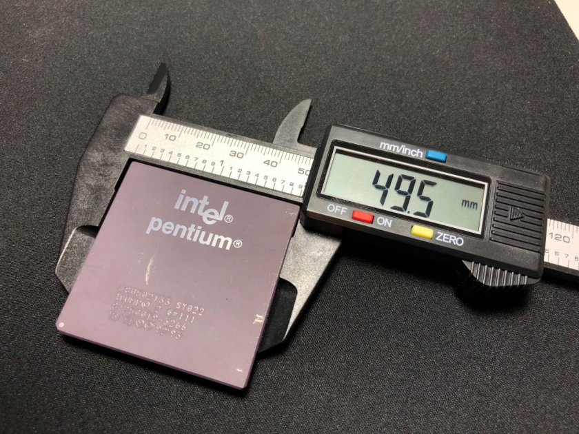
To begin, I used a ‘digital caliper’ tool that I purchased on Amazon for about $15. I can’t say enough how helpful this tool is to get precise measurements – it makes designing your objects so much easier.

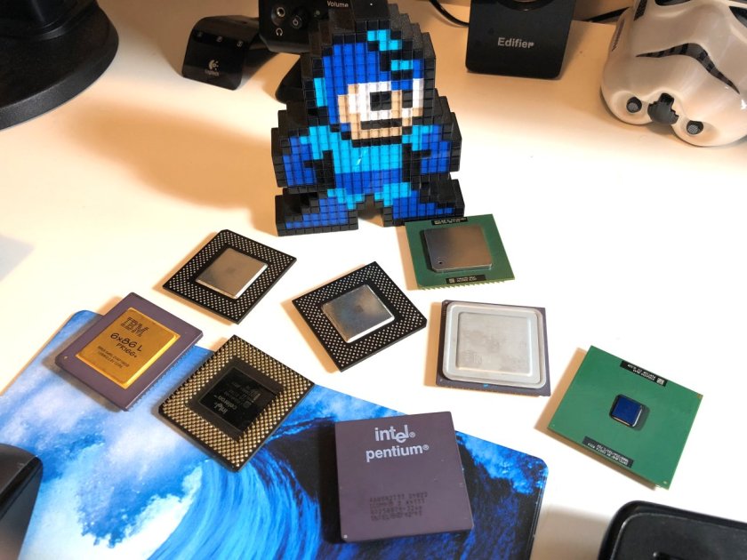
To make sure the tray would work with a wide variety of socket 7 and socket 370 processors, I took a sample of each type I had in my collection:

  • Intel Pentium P54C (133MHz, ceramic top)
  • Intel Celeron Mendocino (400MHz, metal heatspreader). Same design and dimensions as later Pentium MMX CPUs.
  • Intel Pentium 3 (1000MHz Coppermine, no heatspreader)
  • Intel Pentium 3 (1400MHz, Tulatin, different heatspreader design)
  • Cyrix 6x86L (133MHz, gold-top, short heatspreader)
  • AMD K6-2 (500MHz, full heatspreader)
  • AMD K5 (100MHz, similar to Cyrix heatspreader).

Measuring all of these processors got me to the following conclusions:

  • The dimensions varied very slightly, but all were about 49.5mmx49.5mm +/- 0.1mm.
  • Pin height is 3mm on all CPUs
  • Most CPUs had a notch out of the corner, but some didn’t – like Coppermine P3s.
  • CPU thickness (not including pin height) varied from processor to processor due to the heatspreader designs. The thinnest was the P3 coppermine at only 2mm where the exposed core is located. The thickest was the Tulatin at 3.4mm.

Continue reading “3D Printing CPU Trays”

VMware Tools 10.3.2 Now Available

New bundled VMXNET3 driver corrects PSOD crash issue.

As mentioned in a recent post, a problem in the tools 10.3.0 bundled VMXNET3 driver could cause host PSODs and connectivity issues. As of September 12th, VMware Tools 10.3.2 is now available, which corrects this issue.

The problematic driver was version 1.8.3.0 in tools 10.3.0. According to the release notes, it has been replaced with version 1.8.3.1. In addition to this fix, there are four resolved issues listed as well.

VMware mentions the following in the 10.3.2 release notes:

Note: VMware Tools 10.3.0 is deprecated due to a VMXNET3 driver related issue. For more information, see KB 57796. Install VMware Tools 10.3.2, or VMware Tools 10.2.5 or an earlier version of VMware Tools.”

Kudos to the VMware engineering teams for getting 10.3.2 released so quickly after the discovery of the problem!

Relevant links:


Manual Upgrade of NSX Host VIBs

Complete manual control of the NSX host VIB upgrade process without the use of vSphere DRS.

NSX host upgrades are well automated these days. By taking advantage of ‘fully automated’ DRS, hosts in a cluster can be evacuated, put in maintenance mode, upgraded, and even rebooted without any user intervention. By relying on DRS for resource scheduling, NSX doesn’t have to worry about doing too many hosts simultaneously and the process can generally be done without end-users even noticing.

But what if you don’t want this level of automation? Maybe you’ve got very sensitive VMs that can’t be migrated, or VMs pinned to hosts for some reason. Or maybe you just want maximum control of the upgrade process and which hosts are upgraded – and when.

There is no reason why you can’t have full control of the host upgrade process and leave DRS in manual mode. This is indeed supported.

Most of the documentation and guides out there assume that people will want to take advantage of DRS-driven upgrades, but this doesn’t mean it’s the only supported method. There is no reason why you can’t have full control of the host upgrade process and this is indeed supported. Today I’ll be walking through this in my lab as I upgrade to NSX 6.4.1.

Step 1 – Clicking the Upgrade Link

Once you’ve upgraded your NSX manager and control cluster, you should be ready to begin tackling your ESXi host clusters. Before you proceed, you’ll need to ensure your host clusters have DRS set to ‘Manual’ mode. Don’t disable DRS – that will get rid of your resource pools. Manual mode is sufficient.

Next, you’ll need to browse to the usual ‘Installation’ section in the UI, and click on the ‘Host Preparation’ tab. From here, it’s now safe to click the ‘Upgrade Available’ link on the cluster to begin the upgrade process. Because DRS is in manual mode, nothing will be able happen. Hosts can’t be evacuated, and as a result, VIBs can’t be upgraded. In essence, the upgrade has started, but immediately stalls and awaits manual intervention.


upgnodrs-3
This upgrade is essentially hung up waiting for hosts to enter maintenance mode.


In 6.4.1 as shown above, a clear banner message is displayed reminding you that DRS is in manual mode and that hosts must be manually put in maintenance mode.

Continue reading “Manual Upgrade of NSX Host VIBs”

Home Lab Power Automation – Part 3

In part 2, I shared the PowerCLI scripting I used to power on my entire lab environment in the correct order. In this final installment, I’ll take you through the scripting used to power everything down. Although you may think the process is just the reverse of what I covered in part 2, you’ll see there were some other things to consider and different approaches required.

Step 1 – Shutting Down Compute Cluster VMs

To begin the process, I’d need to shut down all VMs in the compute-a cluster. None of the VMs there are essential for running the lab, so they can be safely stopped at any time. I was able to do this by connecting to vCenter with PowerCLI and then using a ‘foreach’ loop to gracefully shut down any VMs in the ‘Powered On’ state.

"Connecting to vCenter Server ..." |timestamp
Connect-VIServer -Server 172.16.1.15 -User administrator@vsphere.local -Password "VMware9("

"Shutting down all VMs in compute-a ..." |timestamp
$vmlista = Get-VM -Location compute-a | where{$_.PowerState -eq 'PoweredOn'}
foreach ($vm in $vmlista)
    {
    Shutdown-VMGuest -VM $vm -Confirm:$false | Format-List -Property VM, State
    }

The above scripting ensures the VMs start shutting down, but it doesn’t tell me that they completed the process. After this is run, it’s likely that one or more VMs may still be online. Before I can proceed, I need to check that they’re all are in a ‘Powered Off’ state.

"Waiting for all VMs in compute-a to shut down ..." |timestamp
do
{
    "The following VM(s) are still powered on:"|timestamp
    $pendingvmsa = (Get-VM -Location compute-a | where{$_.PowerState -eq 'PoweredOn'})
    $pendingvmsa | Format-List -Property Name, PowerState
    sleep 1
} until($pendingvmsa -eq $null)
"All VMs in compute-a are powered off ..."|timestamp

A ‘do until’ loop does the trick here. I simply populate the list of all powered on VMs into the $pendingvmsa variable and print that list. After a one second delay, the loop continues until the $pendingvmsa variable is null. When it’s null, I know all of the VMs are powered off and I can safely continue.

Continue reading “Home Lab Power Automation – Part 3”

Home Lab Power Automation – Part 2

In part 1, I shared some of the tools I’d use to execute the power on and shutdown tasks in my lab. Today, let’s have a look at my startup PowerCLI script.

A Test-Connection Cmdlet Replacement

As I started working on the scripts, I needed a way to determine if hosts and devices were accessible on the network. Unfortunately, the Test-Connection cmdlet was not available in the Linux PowerShell core release. It uses the Windows network stack to do its thing, so it may be a while before an equivalent gets ported to Linux. As an alternative, I created a simple python script that achieves the same overall result called pinghost.py. You can find more detail on how it works in a post I did a few months back here.

The script is very straightforward. You specify up to three space separated IP addresses or host names as command line arguments, and the script will send one ICMP echo request to each of the hosts. Depending on the response, it will output either ‘is responding’ or ‘is not responding’. Below is an example:

pi@raspberrypi:~/scripts $ python pinghost.py vc.lab.local 172.16.10.67 172.16.10.20
vc.lab.local is not responding
172.16.10.67 is responding
172.16.10.20 is not responding

Then using this script, I could create sleep loops in PowerShell to wait for one or more devices to become responsive before proceeding.

Adding Timestamps to Script Output

As I created the scripts, I wanted to record the date/time of each event and output displayed. In a sense, I wanted it to look like a log that could be written to a file and referred to later if needed. To do this, I found a simple PowerShell filter that could be piped to each command I ran:

#PowerShell filter to add date/timestamps
filter timestamp {"$(Get-Date -Format G): $_"}

Step 1 – Power On the Switch

Powering up the switch requires the use of the tplink_smartplug.py python script that I discussed in part 1. The general idea here is to instruct the smart plug to set its relay to a state of ‘1’. This brings the switch to life. I then get into a ‘do sleep’ loop in PowerCLI until the Raspberry Pi is able to ping the management interface of the switch. More specifically, it will wait until the pinghost.py script returns a string of “is responding”. If that string isn’t received, it’ll wait two seconds, and then try again.

"Powering up the 10G switch ..." |timestamp
/home/pi/scripts/tplink-smartplug-master/tplink_smartplug.py -t 192.168.1.199 -c on |timestamp

"Waiting for 10G switch to boot ..." |timestamp
do
{
$pingresult = python ~/scripts/pinghost.py 172.16.1.1 |timestamp
$pingresult
sleep 2
} until($pingresult -like '*is responding*')

When run, the output looks similar to the following:

Continue reading “Home Lab Power Automation – Part 2”

Home Lab Power Automation – Part 1

My home lab has grown substantially over the last few years and with it, so did power consumption, heat and noise. I selected power efficient parts where possible, but even with 500-600W power usage, 24/7 operation adds up. I can certainly notice the extra cost on my hydro bill, but it’s not just the financial impact – it’s also the environmental impact I’m concerned about.

The bottom line is that I have no reason to run the lab 24/7. I generally use it an hour or two each day – sometimes more, sometimes less. But there are also stretches where I won’t use it for several days like on weekends or when I’m busy with other things.

I found myself manually shutting down the lab when I knew I wouldn’t be using it and then manually powering everything back up. As you can imagine, this was quite a process. Everything had to be powered on or shut down in a very specific order to avoid problems. I’d also need to be standing in front of the equipment for part of this process as some equipment didn’t have remote power-on capability. Because of the work and time involved, I’d inevitably just leave it powered on for much longer stretches than I needed to.

It wasn’t until I added a 10Gbps Quanta LB6M switch to the lab that I realized I needed to do something. It’s not a quiet or energy efficient switch, consuming an average of 120W at idle.

Continue reading “Home Lab Power Automation – Part 1”

Home Lab

One of the most important tools I use day-to-day is my lab. Although I’m fortunate to have access to some shared lab resources at VMware, I still choose to maintain a dedicated home lab. I like to have the freedom to build it up, tear it down and configure it in any way I see fit.

I’ve had a few people ask me about my home lab recently, so I wanted to take a moment to share my setup. I’m not going to go too much into how I use the lab, or the software side of things but will stay focused on the hardware for now.

My Goals

I’ve had several iterations of home lab over the years, but my most recent overhaul was done about two years ago in 2016. At that time, I had several goals in mind:

  1. To keep cost low. I chose mainly EOL, second hand hardware that was relatively inexpensive. I often looked for the ‘sweet spot’ to get the best performance for the dollar.
  2. To use server/workstation grade hardware wherever possible. I’ve had some mixed experiences with consumer grade equipment and prefer having IPMI and being able to run large amounts of registered ECC memory.
  3. Low noise. I really didn’t like the noise and heat generated by rackmount gear and tried to stick with custom-build server systems wherever possible.
  4. Power efficiency. Building custom machines with simple cooling systems allowed me to keep power consumption down. I also didn’t see the point of running the lab 24/7 and chose to automate power on and power off activities.
  5. Sized right. Although more RAM and compute power is always desirable, I tried to keep things reasonably sized to keep costs and power consumption down. I wanted to be able to have some flexibility, but would try to keep VMs sized smaller and power down what I didn’t need.

The Lab

homelabv1

I’ll get more into each component, but here’s a summary:

  • 1x Management Node (2x Xeon E5-2670, 96GB RAM)
  • 3x Compute Nodes (Xeon X3440, 16GB RAM)
  • 1x FreeNAS Server (Dell T110, Xeon 3430, 8GB RAM)
  • 1x Raspberry Pi 3 Model B (Automation and remote access)
  • Quanta LB6M 24 port 10Gbps Switch (24x SFP+ ports)
  • D-link DGS-1210-16 Managed Switch (16x copper ports, 4x SFP)
  • Cyber Power PFCLCD1500 UPS system

All of the equipment sits comfortably in a wire shelf/rack in a corner of my unfinished basement. Here it can stay nice and cool and the noise it generates doesn’t bother anyone.

Continue reading “Home Lab”

Jumbo Frames and VXLAN Performance

Using an 8900 MTU for better VXLAN throughput and lower packet rates.

VXLAN overlay technology is part of what makes software defined networking possible. By encapsulating full frames into UDP datagrams, L2 networks can be stretched across all manners of routed topologies. This breaks down the barriers of physical networking and builds the foundation for the software defined datacenter.

VXLAN or Virtual Extensible LAN is an IETF standard documented in RFC 7348. L2 over routed topologies is made possible by encapsulating entire L2 frames into UDP datagrams. About 50 bytes of outer header data is added to every L2 frame because of this, meaning that for every frame sent on a VXLAN network, both an encapsulation and de-encapsulation task must be performed. This is usually performed by ESXi hosts in software but can sometimes be offloaded to physical network adapters as well.

In a perfect world, this would be done without any performance impact whatsoever. The reality, however, is that software defined wizardry often does have a small performance penalty associated with it. This is unavoidable, but that doesn’t mean there isn’t anything that can be done to help to minimize this cost.

If you’ve been doing some performance testing, you’ve probably noticed that VMware doesn’t post statements like “You can expect X number of Gbps on a VXLAN network”. This is because there are simply too many variables to consider. Everything from NIC type, switches, drivers, firmware, offloading features, CPU count and frequency can play a role here. All these factors must be considered. From my personal experience, I can say that there is a range – albeit a somewhat wide one – of what I’d consider normal. On a modern 10Gbps system, you can generally expect more than 4Gbps but less than 7Gbps with a 1500 MTU. If your NIC supports VXLAN offloading, this can sometimes be higher than 8Gbps. I don’t think I’ve ever seen a system achieve line-rate throughput on a VXLAN backed network with a 1500 MTU regardless of the offloading features employed.

What if we can reduce the amount of encapsulation and de-encapsulation that is so taxing on our hypervisors? Today I’m going to take an in-depth look at just this – using an 8900 MTU to reduce packet rates and increase throughput. The results may surprise you!

Continue reading “Jumbo Frames and VXLAN Performance”

No Bridged Adapters in VMware Workstation

Although I only support vSphere and VMware’s enterprise products, I use VMware Workstation every day. My work laptop runs Windows 10, but I maintain a couple of Linux VMs for day to day use as well. After a large Windows 10 feature update – 1709 I believe – I noticed that my Linux VMs were booting up without any networking. Their virtual adapters were simply reporting ‘link down’.

I had not changed any of the Workstation network configuration since I had installed it and always just used the defaults. For my guest VMs, I had always preferred to use ‘Bridged’ networking rather than NAT:

wsnets-1

What I found odd was that the VMnet0 connection usually associated with bridging was nowhere to be found in the ‘Virtual Network Editor’.

wsnets-2

When trying to add a new bridged network, I’d get the following error:

wsnets-3

The exact text is:

“Cannot change network to bridged: There are no un-bridged host network adapters.”

Clearly, Workstation thinks the adapters are already bridged despite there not being any listed in the virtual network editor.

Continue reading “No Bridged Adapters in VMware Workstation”

NSX Troubleshooting Scenario 11 – Solution

Welcome to the eleventh installment of a new series of NSX troubleshooting scenarios. Thanks to everyone who took the time to comment on the first half of the scenario. Today I’ll be performing some troubleshooting and will show how I came to the solution.

Please see the first half for more detail on the problem symptoms and some scoping.

Getting Started

As you’ll recall in the first half, our fictional customer was seeing some HA heartbeat channel alarms in the new HTML5 NSX dashboard.

tshoot11a-1

After doing some digging, we were able to determine that the ESG had an interface configured for HA on VLAN 16 and that from the CLI, the edge really was complaining about being unable to reach its peer.

tshoot11a-3

You probably noticed in the first half, that the HA interface doesn’t have an IP address configured. This may look odd, but it’s fine. Even if you did specify a custom /30 IP address for HA purposes, it would not show up as an interface IP address here. Rather, you’d need to look for one specified in the HA configuration settings here:

Continue reading “NSX Troubleshooting Scenario 11 – Solution”